TX 3W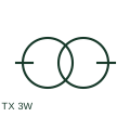
Three-winding transformer
A three-winding transformer couples three windings through its magnetic system.
SLD / Schematic
Two six-pulse bridges fed from star and delta transformer windings 30 degrees apart, cancelling the lowest harmonics.
In plain English
A twelve-pulse rectifier feeds two six-pulse bridges from transformer secondaries displaced by 30 electrical degrees, usually one star and one delta winding. The two bridge outputs are combined in series or in parallel with an interphase reactor, and the 5th and 7th harmonic currents cancel on the primary side.
The single-line diagram shows a three-winding rectifier transformer with star and delta secondaries, each feeding a rectifier block, and the two DC outputs joining. It is used for large UPS rectifiers, electrolysers, traction substations and some drive front ends.
Cancellation only works when the two bridges share load equally and the supply is balanced. The symbol does not show residual 11th and 13th harmonics or the effect of transformer impedance mismatch, so a harmonic study is still required.
Two six-pulse bridges fed from star and delta transformer windings 30 degrees apart, cancelling the lowest harmonics. A twelve-pulse rectifier uses two phase-shifted bridges; a six-pulse rectifier uses one bridge and has larger 5th and 7th harmonics.
Read the source: AutoCAD Electrical: Three-phase transformer connections · IEC graphical symbols for diagrams

A twelve-pulse rectifier feeds two six-pulse bridges from transformer secondaries displaced by 30 electrical degrees, usually one star and one delta winding. The two bridge outputs are combined in series or in parallel with an interphase reactor, and the 5th and 7th harmonic currents cancel on the primary side.
The single-line diagram shows a three-winding rectifier transformer with star and delta secondaries, each feeding a rectifier block, and the two DC outputs joining. It is used for large UPS rectifiers, electrolysers, traction substations and some drive front ends.
Cancellation only works when the two bridges share load equally and the supply is balanced. The symbol does not show residual 11th and 13th harmonics or the effect of transformer impedance mismatch, so a harmonic study is still required.
A twelve-pulse rectifier uses two phase-shifted bridges; a six-pulse rectifier uses one bridge and has larger 5th and 7th harmonics.
These public references support the explanation and provide further detail. Their graphics and downloadable files remain with their publishers.
Public three-phase transformer connection symbol family for star and delta secondaries.
IEC graphical symbol context for converters.
This illustration was authored independently by Elora Grid to explain the concept. It is not reproduced from a customer drawing, an official standard graphic or a manufacturer CAD file. Its correspondence to an exact IEC or IEEE symbol identifier has not been certified.
SVG and DXF downloads contain this original artwork. DXF uses unscaled drawing units; a GA envelope supplies no product dimensions, clearances or fabrication information. Original artwork is available under CC BY 4.0. Third-party references retain their own terms.
A three-winding transformer couples three windings through its magnetic system.
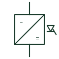
An AC-to-DC converter using thyristors fired at a controlled angle to set its DC output voltage.
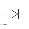
A three-phase bridge rectifier converts a documented three-phase AC input into a DC output.
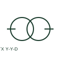
A star-star-delta transformer includes two star-connected winding sets and a delta tertiary winding.
Elora Grid helps electrical teams work with drawings, specifications and equipment information. Explore the drafting workflow or join the early-access waitlist.