RMU
Ring main unit
A secondary-distribution switchgear assembly with a selected combination of switching functions.
GA objects
Capacitively coupled indicator on MV switchgear that shows whether each phase of a cable or busbar is energised.
In plain English
Voltage presence indicating systems are built into medium-voltage switchgear and ring main units. A capacitive divider in the bushing or insulator feeds a low-voltage indicator for each phase, and test sockets allow phase comparison before connecting cables or closing onto another source.
An indicator showing no voltage is not proof that the circuit is dead. Safe isolation still requires the approved test method and earthing procedure, and the symbol does not show the indicator's thresholds or whether it is self-testing.
Check one indicator per phase is shown. Do not treat a dark indicator as proof of isolation. A VPIS indicates presence of voltage; a voltmeter measures its value.
Capacitively coupled indicator on MV switchgear that shows whether each phase of a cable or busbar is supplied with operating power. A VPIS indicates presence of voltage; a voltmeter measures its value.
Read the source: Secondary-distribution switchgear and ring main units · IEC graphical symbols for diagrams

Voltage presence indicating systems are built into medium-voltage switchgear and ring main units. A capacitive divider in the bushing or insulator feeds a low-voltage indicator for each phase, and test sockets allow phase comparison before connecting cables or closing onto another source.
An indicator showing no voltage is not proof that the circuit is dead. Safe isolation still requires the approved test method and earthing procedure, and the symbol does not show the indicator's thresholds or whether it is self-testing.
A VPIS indicates presence of voltage; a voltmeter measures its value.
These public references support the explanation and provide further detail. Their graphics and downloadable files remain with their publishers.
Public secondary-distribution switchgear context where voltage presence indication is fitted.
IEC context for graphical symbols used in diagrams; no IEC graphic is reproduced.
This illustration was authored independently by Elora Grid to explain the concept. It is not reproduced from a customer drawing, an official standard graphic or a manufacturer CAD file. Its correspondence to an exact IEC or IEEE symbol identifier has not been certified.
SVG and DXF downloads contain this original artwork. DXF uses unscaled drawing units; a GA envelope supplies no product dimensions, clearances or fabrication information. Original artwork is available under CC BY 4.0. Third-party references retain their own terms.
A secondary-distribution switchgear assembly with a selected combination of switching functions.
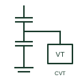
An instrument transformer using a capacitive voltage divider and an electromagnetic unit to supply documented voltage measurement or protection signals.

A voltmeter indicates electrical potential difference between its measurement inputs.
Elora Grid helps electrical teams work with drawings, specifications and equipment information. Explore the drafting workflow or join the early-access waitlist.