VT / PT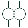
Voltage transformer
A transformer providing a voltage signal for metering or protection.
SLD / Schematic
VT with two separate secondary windings, typically one for metering and one for protection, each with its own fusing.
In plain English
This VT form has one primary and two secondary windings. The usual arrangement gives a metering winding with a high accuracy class and a protection winding, each fused or protected by an MCB separately so a fault on one circuit does not take out the other.
Both windings share the same core, so their combined burden must stay within the VT's thermal rating. The symbol shows the two windings but not the class of each or the secondary protection, which must be stated for each circuit.
Read the class and burden of each winding. Find the separate secondary protection for each winding. A VT with two secondaries shares one core; two separate VTs give independent cores.
VT with two separate secondary windings, typically one for metering and one for protection, each with its own fusing. A VT with two secondaries shares one core; two separate VTs give independent cores.
Read the source: Indoor current and voltage transformers · Power, potential and autotransformer symbols

This VT form has one primary and two secondary windings. The usual arrangement gives a metering winding with a high accuracy class and a protection winding, each fused or protected by an MCB separately so a fault on one circuit does not take out the other.
Both windings share the same core, so their combined burden must stay within the VT's thermal rating. The symbol shows the two windings but not the class of each or the secondary protection, which must be stated for each circuit.
A VT with two secondaries shares one core; two separate VTs give independent cores.
These public references support the explanation and provide further detail. Their graphics and downloadable files remain with their publishers.
Public manufacturer overview of indoor current and voltage instrument transformers.
Public potential-transformer symbol family used for context.
This illustration was authored independently by Elora Grid to explain the concept. It is not reproduced from a customer drawing, an official standard graphic or a manufacturer CAD file. Its correspondence to an exact IEC or IEEE symbol identifier has not been certified.
SVG and DXF downloads contain this original artwork. DXF uses unscaled drawing units; a GA envelope supplies no product dimensions, clearances or fabrication information. Original artwork is available under CC BY 4.0. Third-party references retain their own terms.
A transformer providing a voltage signal for metering or protection.
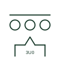
Three single-phase VTs whose residual windings are connected in broken delta to produce the zero-sequence voltage.
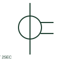
A CT with two secondary windings supplies two documented secondary circuits.
Elora Grid helps electrical teams work with drawings, specifications and equipment information. Explore the drafting workflow or join the early-access waitlist.