OP-AMP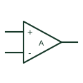
Operational amplifier
An analogue amplifier represented by inverting and non-inverting inputs, an output and its supply connections.
Schematic
Triangle op-amp symbol with minus and plus inputs on the left and the output at the apex.
In plain English
The triangular op-amp symbol is the most common analogue element in North American and manufacturer schematics. The two inputs enter the flat side, marked minus for inverting and plus for non-inverting, and the output leaves from the apex. Supply pins may be drawn on the sloping sides or omitted.
Schematics often flip the triangle vertically to simplify feedback routing, which swaps the positions of minus and plus. Always read the signs, not the positions, when tracing the circuit.
The symbol does not distinguish between general-purpose, precision, rail-to-rail or high-speed parts. The part number and its datasheet decide performance.
Triangle op-amp symbol with minus and plus inputs on the left and the output at the apex. A comparator uses a similar triangle but is designed for open-loop switching, often with an open-collector output.
Read the source: ADA4522-1 — operational amplification · IEEE/ANSI 315-1975: graphic symbols for electrical and electronics diagrams
Distinctive-shape form as used in IEEE/ANSI-style schematics and manufacturer data books. Independent educational drawing; exact standard geometry and compliance are not asserted. The counterpart is the matching functional concept; no equivalence of every detailed standard graphic is asserted.
Shown as an independently authored educational illustration. Use the cited publication and drawing legend to verify the required drafting form.
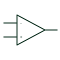
The triangular op-amp symbol is the most common analogue element in North American and manufacturer schematics. The two inputs enter the flat side, marked minus for inverting and plus for non-inverting, and the output leaves from the apex. Supply pins may be drawn on the sloping sides or omitted.
Schematics often flip the triangle vertically to simplify feedback routing, which swaps the positions of minus and plus. Always read the signs, not the positions, when tracing the circuit.
The symbol does not distinguish between general-purpose, precision, rail-to-rail or high-speed parts. The part number and its datasheet decide performance.
A comparator uses a similar triangle but is designed for open-loop switching, often with an open-collector output.
These public references support the explanation and provide further detail. Their graphics and downloadable files remain with their publishers.
Manufacturer operational amplifier documentation.
Graphic-symbol standards context; not a source of reproduced artwork.
This illustration was authored independently by Elora Grid to explain the concept. It is not reproduced from a customer drawing, an official standard graphic or a manufacturer CAD file. Its correspondence to an exact IEC or IEEE symbol identifier has not been certified.
SVG and DXF downloads contain this original artwork. DXF uses unscaled drawing units; a GA envelope supplies no product dimensions, clearances or fabrication information. Original artwork is available under CC BY 4.0. Third-party references retain their own terms.
An analogue amplifier represented by inverting and non-inverting inputs, an output and its supply connections.
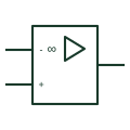
Rectangular IEC-style op-amp drawn as a box with an amplifier triangle and an infinity sign for very high gain.
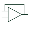
Op-amp with its output tied directly to the inverting input, giving unity gain and a low-impedance output.
Elora Grid helps electrical teams work with drawings, specifications and equipment information. Explore the drafting workflow or join the early-access waitlist.