NI-AMP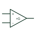
Non-inverting amplifier circuit
Uses an amplifier feedback arrangement to amplify a signal without the intended polarity inversion.
Schematic
Op-amp with its output tied directly to the inverting input, giving unity gain and a low-impedance output.
In plain English
A voltage follower connects the op-amp output straight back to the inverting input and applies the signal to the non-inverting input. The output equals the input, but it is driven from a low impedance, so a high-impedance source can drive a load without being disturbed.
Followers appear as buffers after voltage dividers, references, sensors and sample-and-hold capacitors, and before ADC inputs. On schematics they are easy to recognise by the direct feedback wire with no resistor.
The circuit does not guarantee stability with heavy capacitive loads, and not every op-amp is unity-gain stable. Check the part selection and any isolating resistor at the output.
Op-amp with its output tied directly to the inverting input, giving unity gain and a low-impedance output. A non-inverting amplifier has a resistor divider in the feedback path and gain greater than one.
Read the source: University tutorials: amplifier configurations and signal processing · ADA4522-1 — operational amplification
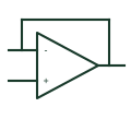
A voltage follower connects the op-amp output straight back to the inverting input and applies the signal to the non-inverting input. The output equals the input, but it is driven from a low impedance, so a high-impedance source can drive a load without being disturbed.
Followers appear as buffers after voltage dividers, references, sensors and sample-and-hold capacitors, and before ADC inputs. On schematics they are easy to recognise by the direct feedback wire with no resistor.
The circuit does not guarantee stability with heavy capacitive loads, and not every op-amp is unity-gain stable. Check the part selection and any isolating resistor at the output.
A non-inverting amplifier has a resistor divider in the feedback path and gain greater than one.
These public references support the explanation and provide further detail. Their graphics and downloadable files remain with their publishers.
Public tutorial material on op-amp configurations including the follower.
Manufacturer operational amplifier documentation.
This illustration was authored independently by Elora Grid to explain the concept. It is not reproduced from a customer drawing, an official standard graphic or a manufacturer CAD file. Its correspondence to an exact IEC or IEEE symbol identifier has not been certified.
SVG and DXF downloads contain this original artwork. DXF uses unscaled drawing units; a GA envelope supplies no product dimensions, clearances or fabrication information. Original artwork is available under CC BY 4.0. Third-party references retain their own terms.
Uses an amplifier feedback arrangement to amplify a signal without the intended polarity inversion.
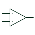
Triangle op-amp symbol with minus and plus inputs on the left and the output at the apex.
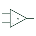
An analogue amplifier represented by inverting and non-inverting inputs, an output and its supply connections.
Elora Grid helps electrical teams work with drawings, specifications and equipment information. Explore the drafting workflow or join the early-access waitlist.