OC-BUF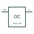
Open-collector buffer
Provides a logic output through a transistor pull-down stage requiring the documented external load or pull-up.
Schematic
Several open-collector outputs joined on one pulled-up line, so any output pulling low makes the line low.
In plain English
A wired-AND connection is formed by joining open-collector or open-drain outputs to a single line with one pull-up. The line is high only when every output is off, so in positive logic the result is the AND of the individual output states. Some schematics draw a small AND outline around the junction to make the implied function visible.
Shared interrupt lines, ready signals and I2C-style buses rely on this arrangement. A drawing should show every output on the net, the single pull-up, and the supply, because adding or removing a driver changes the logic and the pull-up current.
The connection only works with open-circuit outputs. Joining push-pull outputs in the same way causes contention and possible damage, so the output type of each gate must be checked.
Several open-collector outputs joined on one pulled-up line, so any output pulling low makes the line low. A wired-OR uses open-emitter outputs with a pull-down; wired-AND uses open-collector outputs with a pull-up.
Read the source: Overview of IEEE Standard 91-1984: explanation of logic symbols (SDYZ001A) · SNx4HC05 hex inverters with open-drain outputs
Distinctive-shape form as used in IEEE/ANSI-style schematics and manufacturer data books. Independent educational drawing; exact standard geometry and compliance are not asserted.
Shown as an independently authored educational illustration. Use the cited publication and drawing legend to verify the required drafting form.
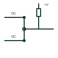
A wired-AND connection is formed by joining open-collector or open-drain outputs to a single line with one pull-up. The line is high only when every output is off, so in positive logic the result is the AND of the individual output states. Some schematics draw a small AND outline around the junction to make the implied function visible.
Shared interrupt lines, ready signals and I2C-style buses rely on this arrangement. A drawing should show every output on the net, the single pull-up, and the supply, because adding or removing a driver changes the logic and the pull-up current.
The connection only works with open-circuit outputs. Joining push-pull outputs in the same way causes contention and possible damage, so the output type of each gate must be checked.
A wired-OR uses open-emitter outputs with a pull-down; wired-AND uses open-collector outputs with a pull-up.
These public references support the explanation and provide further detail. Their graphics and downloadable files remain with their publishers.
States that open-collector outputs are capable of positive-logic wired-AND connection.
Manufacturer open-drain output documentation.
This illustration was authored independently by Elora Grid to explain the concept. It is not reproduced from a customer drawing, an official standard graphic or a manufacturer CAD file. Its correspondence to an exact IEC or IEEE symbol identifier has not been certified.
SVG and DXF downloads contain this original artwork. DXF uses unscaled drawing units; a GA envelope supplies no product dimensions, clearances or fabrication information. Original artwork is available under CC BY 4.0. Third-party references retain their own terms.
Provides a logic output through a transistor pull-down stage requiring the documented external load or pull-up.
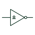
Inverter triangle with output bubble and an open-circuit mark, needing an external pull-up to produce a high level.
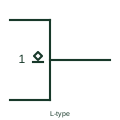
Underlined diamond inside an outline: an open-circuit output that can only drive a low level.
Elora Grid helps electrical teams work with drawings, specifications and equipment information. Explore the drafting workflow or join the early-access waitlist.