HYB INV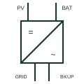
Hybrid inverter
A single inverter with PV, battery and AC ports, combining MPPT charging, battery inversion and backup output.
SLD
A battery converter that charges from an AC source and inverts back to AC, with an internal transfer relay for the load.
In plain English
An inverter-charger contains one bidirectional power stage between a battery and an AC output, together with an internal transfer relay connecting the AC input to the output when a valid source is present. With the source available it passes power through and charges the battery; without it, it opens the relay and inverts from the battery.
Drawings show a converter box with DC and AC marks, a bidirectional arrow, an AC input from the grid or generator and an AC output to the load. The transfer relay may be drawn inside the boundary as a changeover contact, and some units have a second output that drops during battery operation.
The symbol does not show the internal neutral-earth relay many units use when inverting, which matters for earthing and residual current device operation. Power assist settings, which let the inverter add battery power to a limited generator supply, are also invisible on the drawing.
A battery converter that charges from an AC source and inverts back to AC, with an internal transfer relay for the load. An inverter-charger has an internal transfer relay and charger; a plain DC-to-AC inverter only converts battery power to AC.
Read the source: MultiPlus-II official product and documents · Quattro official product and documents
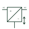
An inverter-charger contains one bidirectional power stage between a battery and an AC output, together with an internal transfer relay connecting the AC input to the output when a valid source is present. With the source available it passes power through and charges the battery; without it, it opens the relay and inverts from the battery.
Drawings show a converter box with DC and AC marks, a bidirectional arrow, an AC input from the grid or generator and an AC output to the load. The transfer relay may be drawn inside the boundary as a changeover contact, and some units have a second output that drops during battery operation.
The symbol does not show the internal neutral-earth relay many units use when inverting, which matters for earthing and residual current device operation. Power assist settings, which let the inverter add battery power to a limited generator supply, are also invisible on the drawing.
An inverter-charger has an internal transfer relay and charger; a plain DC-to-AC inverter only converts battery power to AC.
These public references support the explanation and provide further detail. Their graphics and downloadable files remain with their publishers.
Public inverter-charger product and document page.
Public dual-input inverter-charger documentation.
This illustration was authored independently by Elora Grid to explain the concept. It is not reproduced from a customer drawing, an official standard graphic or a manufacturer CAD file. Its correspondence to an exact IEC or IEEE symbol identifier has not been certified.
SVG and DXF downloads contain this original artwork. DXF uses unscaled drawing units; a GA envelope supplies no product dimensions, clearances or fabrication information. Original artwork is available under CC BY 4.0. Third-party references retain their own terms.
A single inverter with PV, battery and AC ports, combining MPPT charging, battery inversion and backup output.
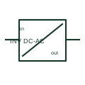
A DC/AC inverter converts a documented DC supply into an AC output.
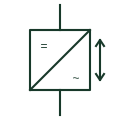
The bidirectional inverter stage of a battery plant that charges and discharges the DC battery from the AC network.
An inverter-charger interfaces a battery circuit with the specified AC supply/load system.
Elora Grid helps electrical teams work with drawings, specifications and equipment information. Explore the drafting workflow or join the early-access waitlist.