BESS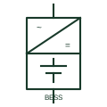
Battery energy storage system
A complete battery plant block combining batteries, power conversion and controls, shown as one source or sink on an SLD.
SLD
The bidirectional inverter stage of a battery plant that charges and discharges the DC battery from the AC network.
In plain English
The power conversion system is the bidirectional converter that sits between the battery DC bus and the AC network in a storage plant. It charges the battery by rectifying AC and discharges it by inverting DC, under the direction of a plant controller that sets active and reactive power or operates in a grid-forming mode.
Drawings show a converter box with both AC and DC marks and a bidirectional energy-flow arrow, a DC breaker or switch on the battery side, and an AC breaker, filter and often a medium-voltage skid transformer on the network side. Several PCS units may share one transformer.
The symbol does not tell you whether the unit can black-start a dead bus, how much overload it can supply or how it limits fault current. Those features drive protection settings and must be read from the converter specification.
The bidirectional inverter stage of a battery plant that charges and discharges the DC battery from the AC network. A PCS is a utility or commercial storage converter; an inverter-charger is a smaller low-voltage unit with an integral AC transfer relay.
Read the source: Battery energy storage and power conversion · Autodesk IEC-60617 preview: Energy-flow qualifiers
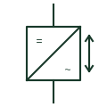
The power conversion system is the bidirectional converter that sits between the battery DC bus and the AC network in a storage plant. It charges the battery by rectifying AC and discharges it by inverting DC, under the direction of a plant controller that sets active and reactive power or operates in a grid-forming mode.
Drawings show a converter box with both AC and DC marks and a bidirectional energy-flow arrow, a DC breaker or switch on the battery side, and an AC breaker, filter and often a medium-voltage skid transformer on the network side. Several PCS units may share one transformer.
The symbol does not tell you whether the unit can black-start a dead bus, how much overload it can supply or how it limits fault current. Those features drive protection settings and must be read from the converter specification.
A PCS is a utility or commercial storage converter; an inverter-charger is a smaller low-voltage unit with an integral AC transfer relay.
These public references support the explanation and provide further detail. Their graphics and downloadable files remain with their publishers.
Public power conversion context for battery storage.
Public IEC-context energy-flow qualifier family used for the bidirectional mark.
This illustration was authored independently by Elora Grid to explain the concept. It is not reproduced from a customer drawing, an official standard graphic or a manufacturer CAD file. Its correspondence to an exact IEC or IEEE symbol identifier has not been certified.
SVG and DXF downloads contain this original artwork. DXF uses unscaled drawing units; a GA envelope supplies no product dimensions, clearances or fabrication information. Original artwork is available under CC BY 4.0. Third-party references retain their own terms.
A complete battery plant block combining batteries, power conversion and controls, shown as one source or sink on an SLD.
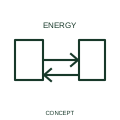
This qualifier identifies an energy interface intended to operate in both directions.
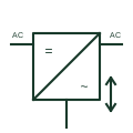
A battery converter that charges from an AC source and inverts back to AC, with an internal transfer relay for the load.
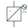
An inverter controlled as a voltage source that sets its own voltage and frequency, able to energise and hold up an island.
Elora Grid helps electrical teams work with drawings, specifications and equipment information. Explore the drafting workflow or join the early-access waitlist.