M WR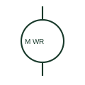
Wound-rotor induction motor
A wound-rotor induction motor includes a rotor winding arrangement with documented external connections.
SLD / Schematic
A wound-rotor induction generator with the stator on the network and the rotor fed through a back-to-back converter sized for slip power.
In plain English
A doubly-fed induction generator has its stator connected directly to the turbine transformer while the rotor windings, reached through slip rings, connect to a back-to-back AC/DC/AC converter. The converter injects rotor currents at slip frequency, allowing variable speed of roughly plus or minus thirty per cent around synchronous speed and independent control of active and reactive power.
On a single-line diagram the generator circle shows two connections: the stator branch to the main breaker and the rotor branch to a pair of converter blocks joined by a DC link. A crowbar or DC chopper is often shown on the rotor converter for fault protection, and a line filter or reactor sits on the grid-side converter.
Because the converter only carries slip power, typically a quarter to a third of the turbine rating, the symbol does not imply full decoupling from the network. Short-circuit contribution, crowbar operation and ride-through capability depend on control settings that the diagram does not show.
A wound-rotor induction generator with the stator on the network and the rotor fed through a back-to-back converter sized for slip power. A DFIG converter handles only rotor slip power; a full-converter turbine passes all generator output through the converter.
Read the source: Bidirectional three-/single-phase AC/DC PFC and inverter application note · Generator symbol variants
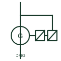
A doubly-fed induction generator has its stator connected directly to the turbine transformer while the rotor windings, reached through slip rings, connect to a back-to-back AC/DC/AC converter. The converter injects rotor currents at slip frequency, allowing variable speed of roughly plus or minus thirty per cent around synchronous speed and independent control of active and reactive power.
On a single-line diagram the generator circle shows two connections: the stator branch to the main breaker and the rotor branch to a pair of converter blocks joined by a DC link. A crowbar or DC chopper is often shown on the rotor converter for fault protection, and a line filter or reactor sits on the grid-side converter.
Because the converter only carries slip power, typically a quarter to a third of the turbine rating, the symbol does not imply full decoupling from the network. Short-circuit contribution, crowbar operation and ride-through capability depend on control settings that the diagram does not show.
A DFIG converter handles only rotor slip power; a full-converter turbine passes all generator output through the converter.
These public references support the explanation and provide further detail. Their graphics and downloadable files remain with their publishers.
Public bidirectional AC/DC converter context relevant to the rotor-side back-to-back stage.
Public generator symbol family context; the DFIG artwork is independently drawn.
This illustration was authored independently by Elora Grid to explain the concept. It is not reproduced from a customer drawing, an official standard graphic or a manufacturer CAD file. Its correspondence to an exact IEC or IEEE symbol identifier has not been certified.
SVG and DXF downloads contain this original artwork. DXF uses unscaled drawing units; a GA envelope supplies no product dimensions, clearances or fabrication information. Original artwork is available under CC BY 4.0. Third-party references retain their own terms.
A wound-rotor induction motor includes a rotor winding arrangement with documented external connections.
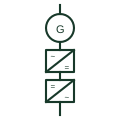
A wind turbine whose entire generator output passes through a full-rated back-to-back converter before reaching the network.
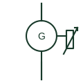
A wind turbine using a wound-rotor induction generator with controlled external rotor resistance to widen the slip range.
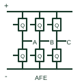
An actively switched AC/DC stage using a documented current-control and DC-link regulation arrangement.
Elora Grid helps electrical teams work with drawings, specifications and equipment information. Explore the drafting workflow or join the early-access waitlist.