M WR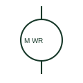
Wound-rotor induction motor
A wound-rotor induction motor includes a rotor winding arrangement with documented external connections.
SLD / Schematic
A wind turbine using a wound-rotor induction generator with controlled external rotor resistance to widen the slip range.
In plain English
A Type 2 wind turbine uses a wound-rotor induction generator whose rotor circuit is connected to a variable resistance, usually switched by power electronics mounted on the rotor. Raising the rotor resistance lets the slip increase to around ten per cent, which softens torque peaks from gusts while the stator stays connected directly to the network.
Drawings show the generator circle with rotor slip-ring or rotor-winding marks and a resistor element with a variable arrow attached to the rotor side. The stator side follows the same path as a Type 1 machine: soft starter, capacitor compensation and step-up transformer.
Energy dissipated in the rotor resistance is lost as heat, so the symbol says nothing about efficiency or about any capability to deliver reactive power. Fault ride-through behaviour and resistor ratings must be read from the turbine model data.
A wind turbine using a wound-rotor induction generator with controlled external rotor resistance to widen the slip range. A Type 2 turbine dissipates rotor energy in resistance; a doubly-fed generator returns rotor power to the network through a converter.
Read the source: AutoCAD Electrical: Power station and substation concepts · Resistors and heater-element symbols
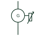
A Type 2 wind turbine uses a wound-rotor induction generator whose rotor circuit is connected to a variable resistance, usually switched by power electronics mounted on the rotor. Raising the rotor resistance lets the slip increase to around ten per cent, which softens torque peaks from gusts while the stator stays connected directly to the network.
Drawings show the generator circle with rotor slip-ring or rotor-winding marks and a resistor element with a variable arrow attached to the rotor side. The stator side follows the same path as a Type 1 machine: soft starter, capacitor compensation and step-up transformer.
Energy dissipated in the rotor resistance is lost as heat, so the symbol says nothing about efficiency or about any capability to deliver reactive power. Fault ride-through behaviour and resistor ratings must be read from the turbine model data.
A Type 2 turbine dissipates rotor energy in resistance; a doubly-fed generator returns rotor power to the network through a converter.
These public references support the explanation and provide further detail. Their graphics and downloadable files remain with their publishers.
Wind station representation used as site-level context.
Public variable-resistor symbol context for the rotor resistance element.
This illustration was authored independently by Elora Grid to explain the concept. It is not reproduced from a customer drawing, an official standard graphic or a manufacturer CAD file. Its correspondence to an exact IEC or IEEE symbol identifier has not been certified.
SVG and DXF downloads contain this original artwork. DXF uses unscaled drawing units; a GA envelope supplies no product dimensions, clearances or fabrication information. Original artwork is available under CC BY 4.0. Third-party references retain their own terms.
A wound-rotor induction motor includes a rotor winding arrangement with documented external connections.
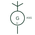
A wind turbine whose squirrel-cage induction generator connects to the network directly, running at nearly constant speed.
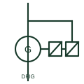
A wound-rotor induction generator with the stator on the network and the rotor fed through a back-to-back converter sized for slip power.
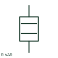
A variable resistor provides a documented adjustable resistance in a circuit path.
Elora Grid helps electrical teams work with drawings, specifications and equipment information. Explore the drafting workflow or join the early-access waitlist.