G 3PH PM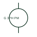
Permanent-magnet synchronous generator
A permanent-magnet synchronous generator provides an AC source using a permanent magnetic excitation system.
SLD / Schematic
A wind turbine whose entire generator output passes through a full-rated back-to-back converter before reaching the network.
In plain English
In a Type 4 turbine the generator, commonly a permanent-magnet or wound-field synchronous machine and sometimes an induction machine, is fully decoupled from the network by a back-to-back converter rated for the whole turbine output. The machine-side converter rectifies variable-frequency generator output to a DC link and the grid-side converter produces network-frequency AC.
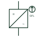
Single-line drawings show the generator circle, a machine-side converter block, a DC link with chopper or brake resistor, a grid-side converter block and the line filter before the step-up transformer. Some drawings collapse this to a generator and a single converter symbol labelled with the conversion direction.
The network sees a converter, not a rotating machine, so fault current is limited to the converter capability and reactive output is a control function. The symbol does not tell you whether the converter is grid-following or grid-forming, which must be checked in the plant control description.
A wind turbine whose entire generator output passes through a full-rated back-to-back converter before reaching the network. A Type 4 turbine routes all power through the converter; a DFIG routes only rotor slip power through it.
Read the source: Generator symbol variants · AutoCAD Electrical: Power station and substation concepts
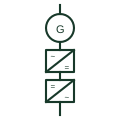
In a Type 4 turbine the generator, commonly a permanent-magnet or wound-field synchronous machine and sometimes an induction machine, is fully decoupled from the network by a back-to-back converter rated for the whole turbine output. The machine-side converter rectifies variable-frequency generator output to a DC link and the grid-side converter produces network-frequency AC.
Single-line drawings show the generator circle, a machine-side converter block, a DC link with chopper or brake resistor, a grid-side converter block and the line filter before the step-up transformer. Some drawings collapse this to a generator and a single converter symbol labelled with the conversion direction.
The network sees a converter, not a rotating machine, so fault current is limited to the converter capability and reactive output is a control function. The symbol does not tell you whether the converter is grid-following or grid-forming, which must be checked in the plant control description.
A Type 4 turbine routes all power through the converter; a DFIG routes only rotor slip power through it.
These public references support the explanation and provide further detail. Their graphics and downloadable files remain with their publishers.
Public permanent-magnet synchronous generator symbol context.
Wind station representation used as site-level context.
This illustration was authored independently by Elora Grid to explain the concept. It is not reproduced from a customer drawing, an official standard graphic or a manufacturer CAD file. Its correspondence to an exact IEC or IEEE symbol identifier has not been certified.
SVG and DXF downloads contain this original artwork. DXF uses unscaled drawing units; a GA envelope supplies no product dimensions, clearances or fabrication information. Original artwork is available under CC BY 4.0. Third-party references retain their own terms.
A permanent-magnet synchronous generator provides an AC source using a permanent magnetic excitation system.
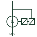
A wound-rotor induction generator with the stator on the network and the rotor fed through a back-to-back converter sized for slip power.
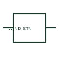
A wind generating station is a system-level representation of a documented wind-generation facility.
An inverter that tracks an existing network voltage with a phase-locked loop and injects controlled current into it.
Elora Grid helps electrical teams work with drawings, specifications and equipment information. Explore the drafting workflow or join the early-access waitlist.