kWh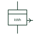
Energy meter with pulse transmitter
Energy meter that sends a pulse output proportional to energy for remote counting, totalising or building management.
SLD / Schematic
Remote register that counts pulses from a transmitting energy meter and repeats its reading at another location.
In plain English
An energy meter repeater has no measuring inputs of its own. It counts pulses from a transmitting meter and displays the resulting energy at a control room or tenant panel, so on the drawing it connects only to a signal circuit rather than to CTs and VTs.
Because it counts pulses, the repeater can drift from the master meter if pulses are lost or the supply is interrupted. The symbol does not show whether it has non-volatile memory or how it is reconciled with the master, which matters if the repeater is used for billing.
Confirm the repeater has no direct measuring inputs. Check the pulse weight matches the transmitting meter. A repeater counts pulses from another meter; a summation meter adds pulses from several meters.
Remote register that counts pulses from a transmitting energy meter and repeats its reading at another location. A repeater counts pulses from another meter; a summation meter adds pulses from several meters.
Read the source: IEC graphical symbols for diagrams
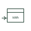
An energy meter repeater has no measuring inputs of its own. It counts pulses from a transmitting meter and displays the resulting energy at a control room or tenant panel, so on the drawing it connects only to a signal circuit rather than to CTs and VTs.
Because it counts pulses, the repeater can drift from the master meter if pulses are lost or the supply is interrupted. The symbol does not show whether it has non-volatile memory or how it is reconciled with the master, which matters if the repeater is used for billing.
A repeater counts pulses from another meter; a summation meter adds pulses from several meters.
These public references support the explanation and provide further detail. Their graphics and downloadable files remain with their publishers.
IEC context for graphical symbols used in diagrams; no IEC graphic is reproduced.
This illustration was authored independently by Elora Grid to explain the concept. It is not reproduced from a customer drawing, an official standard graphic or a manufacturer CAD file. Its correspondence to an exact IEC or IEEE symbol identifier has not been certified.
SVG and DXF downloads contain this original artwork. DXF uses unscaled drawing units; a GA envelope supplies no product dimensions, clearances or fabrication information. Original artwork is available under CC BY 4.0. Third-party references retain their own terms.
Energy meter that sends a pulse output proportional to energy for remote counting, totalising or building management.
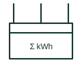
Integrating device that adds energy from several meters or circuits to give one total register.
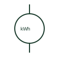
An active-energy meter accumulates active power over time.
Elora Grid helps electrical teams work with drawings, specifications and equipment information. Explore the drafting workflow or join the early-access waitlist.