ΣCT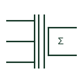
Summation current transformer
Auxiliary CT with several primary windings that adds the secondary currents of other CTs into one output.
Schematic / SLD
Integrating device that adds energy from several meters or circuits to give one total register.
In plain English
A summation meter totalises energy from more than one circuit. It may count pulses from several transmitting meters or, in older schemes, be fed by a summation CT, and it appears where several incomers or feeders must be billed or monitored as one supply.
Every input must use the same direction convention and consistent pulse weights, or the total is wrong. The symbol shows the summing function but not the inputs, so each source meter should be listed with its weighting.
List every meter or circuit that feeds the total. Check pulse weights and directions are consistent. A summation meter totals several circuits; a summation CT adds currents before measurement.
Integrating device that adds energy from several meters or circuits to give one total register. A summation meter totals several circuits; a summation CT adds currents before measurement.
Read the source: IEC graphical symbols for diagrams · Power and energy measurement quantities
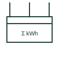
A summation meter totalises energy from more than one circuit. It may count pulses from several transmitting meters or, in older schemes, be fed by a summation CT, and it appears where several incomers or feeders must be billed or monitored as one supply.
Every input must use the same direction convention and consistent pulse weights, or the total is wrong. The symbol shows the summing function but not the inputs, so each source meter should be listed with its weighting.
A summation meter totals several circuits; a summation CT adds currents before measurement.
These public references support the explanation and provide further detail. Their graphics and downloadable files remain with their publishers.
IEC context for graphical symbols used in diagrams; no IEC graphic is reproduced.
Public explanation of energy and power measurement quantities used by meters.
This illustration was authored independently by Elora Grid to explain the concept. It is not reproduced from a customer drawing, an official standard graphic or a manufacturer CAD file. Its correspondence to an exact IEC or IEEE symbol identifier has not been certified.
SVG and DXF downloads contain this original artwork. DXF uses unscaled drawing units; a GA envelope supplies no product dimensions, clearances or fabrication information. Original artwork is available under CC BY 4.0. Third-party references retain their own terms.
Auxiliary CT with several primary windings that adds the secondary currents of other CTs into one output.
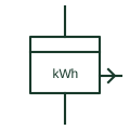
Energy meter that sends a pulse output proportional to energy for remote counting, totalising or building management.
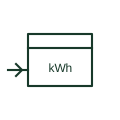
Remote register that counts pulses from a transmitting energy meter and repeats its reading at another location.
Elora Grid helps electrical teams work with drawings, specifications and equipment information. Explore the drafting workflow or join the early-access waitlist.