GFL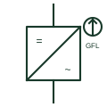
Grid-following inverter
An inverter that tracks an existing network voltage with a phase-locked loop and injects controlled current into it.
SLD
An inverter controlled as a voltage source that sets its own voltage and frequency, able to energise and hold up an island.
In plain English
A grid-forming inverter controls its output as a voltage source behind an impedance, setting voltage magnitude and frequency itself rather than measuring and following them. This lets it start a dead microgrid, share load with other sources through droop or virtual synchronous machine control, and respond instantly to load steps.
Single-line diagrams use the inverter symbol, a box with DC and AC marks, with a GFM label, a voltage-source note or a sine source mark to show the control mode. On microgrid drawings at least one grid-forming source must be available whenever the system is islanded.
Hardware alone does not decide grid-forming behaviour; many converters can switch modes in software. The symbol does not show current limits during faults, which are usually far lower than a synchronous machine, so protection based on fault current needs checking.
An inverter controlled as a voltage source that sets its own voltage and frequency, able to energise and hold up an island. A grid-forming inverter sets voltage and frequency; a grid-following inverter injects current synchronised to a voltage that something else provides.
Read the source: Quattro official product and documents · Reliable hybrid power and microgrid solutions
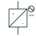
A grid-forming inverter controls its output as a voltage source behind an impedance, setting voltage magnitude and frequency itself rather than measuring and following them. This lets it start a dead microgrid, share load with other sources through droop or virtual synchronous machine control, and respond instantly to load steps.
Single-line diagrams use the inverter symbol, a box with DC and AC marks, with a GFM label, a voltage-source note or a sine source mark to show the control mode. On microgrid drawings at least one grid-forming source must be available whenever the system is islanded.
Hardware alone does not decide grid-forming behaviour; many converters can switch modes in software. The symbol does not show current limits during faults, which are usually far lower than a synchronous machine, so protection based on fault current needs checking.
A grid-forming inverter sets voltage and frequency; a grid-following inverter injects current synchronised to a voltage that something else provides.
These public references support the explanation and provide further detail. Their graphics and downloadable files remain with their publishers.
Public inverter-charger documentation describing island operation.
Public hybrid microgrid context in which a forming source sets voltage and frequency.
This illustration was authored independently by Elora Grid to explain the concept. It is not reproduced from a customer drawing, an official standard graphic or a manufacturer CAD file. Its correspondence to an exact IEC or IEEE symbol identifier has not been certified.
SVG and DXF downloads contain this original artwork. DXF uses unscaled drawing units; a GA envelope supplies no product dimensions, clearances or fabrication information. Original artwork is available under CC BY 4.0. Third-party references retain their own terms.
An inverter that tracks an existing network voltage with a phase-locked loop and injects controlled current into it.
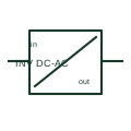
A DC/AC inverter converts a documented DC supply into an AC output.
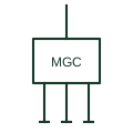
The supervisory controller that dispatches sources, storage and loads and manages islanding and reconnection of a microgrid.
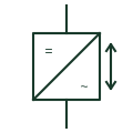
The bidirectional inverter stage of a battery plant that charges and discharges the DC battery from the AC network.
Elora Grid helps electrical teams work with drawings, specifications and equipment information. Explore the drafting workflow or join the early-access waitlist.