J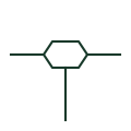
Cable branch joint
A cable joint where a branch cable is taken off a main cable, drawn as a joint with a third cable leaving it.
IEC
A joint connecting two lengths of the same cable in line, drawn as a mark on the cable route.
In plain English
The straight-through joint connects two cable lengths end to end, restoring insulation, screen and sheath continuity. It is shown on cable route drawings and network diagrams at joint bay positions, because joints are the most common failure points on long underground circuits and their locations are needed for fault finding.
The symbol does not show whether screens are cross-bonded at the joint, which is common on high voltage single-core circuits. Cross-bonding links and sheath voltage limiters are separate items on the bonding diagram. It also does not distinguish a joint made between identical cables from one between different types, which is a transition joint.
Note joint locations for fault-location records. Check for screen cross-bonding at the joint. A straight-through joint links two lengths of the same cable; a branch joint takes off a second cable.
A joint connecting two lengths of the same cable in line, drawn as a mark on the cable route. A straight-through joint links two lengths of the same cable; a branch joint takes off a second cable.
Read the source: Elastimold underground cable accessories · IEC-60617 symbol preview directory
Independent IEC-context illustration; not certified IEC geometry.
Shown as an independently authored educational illustration. Use the cited publication and drawing legend to verify the required drafting form.
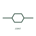
The straight-through joint connects two cable lengths end to end, restoring insulation, screen and sheath continuity. It is shown on cable route drawings and network diagrams at joint bay positions, because joints are the most common failure points on long underground circuits and their locations are needed for fault finding.
The symbol does not show whether screens are cross-bonded at the joint, which is common on high voltage single-core circuits. Cross-bonding links and sheath voltage limiters are separate items on the bonding diagram. It also does not distinguish a joint made between identical cables from one between different types, which is a transition joint.
A straight-through joint links two lengths of the same cable; a branch joint takes off a second cable.
These public references support the explanation and provide further detail. Their graphics and downloadable files remain with their publishers.
Manufacturer context for underground cable joints.
Public directory of IEC-oriented symbol families.
This illustration was authored independently by Elora Grid to explain the concept. It is not reproduced from a customer drawing, an official standard graphic or a manufacturer CAD file. Its correspondence to an exact IEC or IEEE symbol identifier has not been certified.
SVG and DXF downloads contain this original artwork. DXF uses unscaled drawing units; a GA envelope supplies no product dimensions, clearances or fabrication information. Original artwork is available under CC BY 4.0. Third-party references retain their own terms.
A cable joint where a branch cable is taken off a main cable, drawn as a joint with a third cable leaving it.
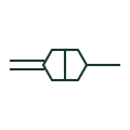
A joint connecting two different cable types, such as paper-insulated to polymeric or land cable to submarine cable.
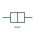
An assembly joining power-cable sections while maintaining the required conductor, insulation, screen and environmental interfaces.
Elora Grid helps electrical teams work with drawings, specifications and equipment information. Explore the drafting workflow or join the early-access waitlist.