SPLICE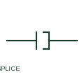
Wire splice
A wire splice intentionally joins documented conductors without a detachable connector interface.
Schematic
An assembly joining power-cable sections while maintaining the required conductor, insulation, screen and environmental interfaces.
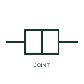
A power cable joint connects cable sections as an installed assembly. The selected joint must be compatible with the cable construction and its conductor, insulation, screen and environmental interfaces.
In a GA or cable-routing drawing, locate the joint bay or connection position and coordinate space for jointing work, cable approach and the completed assembly. Reference the cable schedule and selected manufacturer instructions rather than inferring a kit from a generic outline.
A control-wire splice is a connection concept. A power-cable joint is an installed assembly that must also address insulation, shielding and environmental interfaces for the selected cable.
These public references support the explanation and provide further detail. Their graphics and downloadable files remain with their publishers.
Public manufacturer overview confirms cable joint, splice, termination and grounding accessory applications.
This illustration was authored independently by Elora Grid to explain the concept. It is not reproduced from a customer drawing, an official standard graphic or a manufacturer CAD file. Its correspondence to an exact IEC or IEEE symbol identifier has not been certified.
SVG and DXF downloads contain this original artwork. DXF uses unscaled drawing units; a GA envelope supplies no product dimensions, clearances or fabrication information. Original artwork is available under CC BY 4.0. Third-party references retain their own terms.
A wire splice intentionally joins documented conductors without a detachable connector interface.
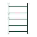
A generic route object connecting cable-support layout to the selected system.
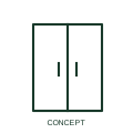
A cable gland secures and, where specified, seals a cable at an enclosure entry.
Elora Grid helps electrical teams work with drawings, specifications and equipment information. Explore the drafting workflow or join the early-access waitlist.