JUNCTION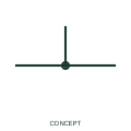
Conductor connection junction
A junction indication marks a documented electrical connection between conductor branches.
Schematic
Four conductors joined using two offset T-junctions rather than one crossing dot, to avoid confusion with a crossing.
In plain English
A four-way connection drawn as a cross with a single dot can be misread if the dot is lost in printing or scanning. The double junction draws the same connection as two T-junctions offset a short distance along the line, each with its own dot, so that the connection survives poor reproduction.
Electrically the double junction is the same node as a dotted cross. It does not represent two separate joints. Drafters use it to make the intent robust, and readers should not count it as an additional connection point or a different wire number unless the drawing shows one.
Treat the two offset tees as one electrical node. Confirm wire numbers are the same on all four branches. A double junction is one node drawn as two offset tees; an unconnected crossing has no node at all.
Four conductors joined using two offset T-junctions rather than one crossing dot, to avoid confusion with a crossing. A double junction is one node drawn as two offset tees; an unconnected crossing has no node at all.
Read the source: Wire connection dots, crossing gaps and loops · IEC-60617 symbol preview directory
Independent IEC-context illustration of a drafting convention; not certified IEC geometry.
Shown as an independently authored educational illustration. Use the cited publication and drawing legend to verify the required drafting form.
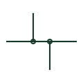
A four-way connection drawn as a cross with a single dot can be misread if the dot is lost in printing or scanning. The double junction draws the same connection as two T-junctions offset a short distance along the line, each with its own dot, so that the connection survives poor reproduction.
Electrically the double junction is the same node as a dotted cross. It does not represent two separate joints. Drafters use it to make the intent robust, and readers should not count it as an additional connection point or a different wire number unless the drawing shows one.
A double junction is one node drawn as two offset tees; an unconnected crossing has no node at all.
These public references support the explanation and provide further detail. Their graphics and downloadable files remain with their publishers.
Public guidance on connection dots and crossing display.
Public directory of IEC-oriented symbol families.
This illustration was authored independently by Elora Grid to explain the concept. It is not reproduced from a customer drawing, an official standard graphic or a manufacturer CAD file. Its correspondence to an exact IEC or IEEE symbol identifier has not been certified.
SVG and DXF downloads contain this original artwork. DXF uses unscaled drawing units; a GA envelope supplies no product dimensions, clearances or fabrication information. Original artwork is available under CC BY 4.0. Third-party references retain their own terms.
A junction indication marks a documented electrical connection between conductor branches.
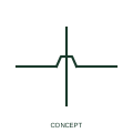
An unconnected crossing shows conductors passing across each other in the drawing without an electrical junction.
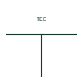
A conductor meeting another at a right angle and stopping there, which IEC practice reads as a connection even without a dot.
Elora Grid helps electrical teams work with drawings, specifications and equipment information. Explore the drafting workflow or join the early-access waitlist.