DYN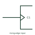
IEC dynamic input (edge-triggered)
Wedge drawn inside the outline at an input, meaning the input acts on a transition rather than a level.
IEC
Clock wedge combined with a negation circle or polarity triangle, so the input acts on a falling edge.
In plain English
Combining the dynamic input wedge with input negation, or with a polarity indicator, means the input is active on the transition from high to low. TI's public overview tabulates how the active transition reads in positive logic, negative logic and polarity notation.
Negative-edge clocking appears in JK flip-flops and some counters, and in designs where two stages are clocked on opposite edges. A reader must check both the wedge and the external mark before deciding which edge the device responds to.
The symbol does not state duty-cycle or minimum pulse width requirements; those come from device timing data. The input waveform must satisfy those limits at the active falling transition, not just reach a valid steady logic level.
Clock wedge combined with a negation circle or polarity triangle, so the input acts on a falling edge. A wedge without an external mark is rising-edge triggered.
Read the source: Overview of IEEE Standard 91-1984: explanation of logic symbols (SDYZ001A) · SN74HC112 — negative-edge JK flip-flops
Qualifying-symbol and dependency conventions as explained in TI's public overview of IEEE Std 91-1984, which incorporates IEC 617-12 work. Independent educational drawing; not certified IEC geometry or an IEC database identifier.
Shown as an independently authored educational illustration. Use the cited publication and drawing legend to verify the required drafting form.
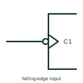
Combining the dynamic input wedge with input negation, or with a polarity indicator, means the input is active on the transition from high to low. TI's public overview tabulates how the active transition reads in positive logic, negative logic and polarity notation.
Negative-edge clocking appears in JK flip-flops and some counters, and in designs where two stages are clocked on opposite edges. A reader must check both the wedge and the external mark before deciding which edge the device responds to.
The symbol does not state duty-cycle or minimum pulse width requirements; those come from device timing data. The input waveform must satisfy those limits at the active falling transition, not just reach a valid steady logic level.
A wedge without an external mark is rising-edge triggered.
These public references support the explanation and provide further detail. Their graphics and downloadable files remain with their publishers.
Tabulates dynamic input forms for each logic convention.
Negative-edge JK flip-flop documentation.
This illustration was authored independently by Elora Grid to explain the concept. It is not reproduced from a customer drawing, an official standard graphic or a manufacturer CAD file. Its correspondence to an exact IEC or IEEE symbol identifier has not been certified.
SVG and DXF downloads contain this original artwork. DXF uses unscaled drawing units; a GA envelope supplies no product dimensions, clearances or fabrication information. Original artwork is available under CC BY 4.0. Third-party references retain their own terms.
Wedge drawn inside the outline at an input, meaning the input acts on a transition rather than a level.
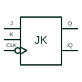
Updates or toggles its stored state from J and K inputs at the selected negative clock edge.
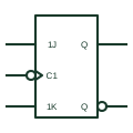
IEC bistable with 1J and 1K inputs controlled by a dynamic C1 clock; J=K=1 toggles the state.
Elora Grid helps electrical teams work with drawings, specifications and equipment information. Explore the drafting workflow or join the early-access waitlist.