HCN1RDUP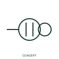
Duplex power receptacle
This form distinguishes a duplex receptacle arrangement.
IEC
Plan mark for a group of socket outlets on one plate, shown by a gang number or stacked outlet strokes.
In plain English
A multiple socket outlet groups two, three or four outlets in one accessory or box. IEC-style plans usually draw a single outlet form with the number of outlets written beside it, or with short parallel strokes on the outlet, instead of drawing each outlet separately.
The number is important for take-off and for load estimates. A desk position shown as a 3-gang outlet with data outlets beside it is a common office pattern; the reader should count the gang number, not the symbol, when scheduling accessories.
The library already lists a duplex receptacle form from a schematic CAD family. This plan mark is the architectural counting form; it does not say whether each outlet is separately switched or whether they share one circuit.
Plan mark for a group of socket outlets on one plate, shown by a gang number or stacked outlet strokes. The duplex receptacle form in schematic libraries shows two outlets graphically; this plan mark counts outlets with a numeral.
Read the source: IEC graphical symbols for diagrams · Autodesk IEC-60617 preview: Single and duplex power-receptacle forms
IEC 60617 installation-plan style (architectural and topographical installation symbols); independently drawn, not certified IEC geometry or a database identifier.
Shown as an independently authored educational illustration. Use the cited publication and drawing legend to verify the required drafting form.
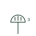
A multiple socket outlet groups two, three or four outlets in one accessory or box. IEC-style plans usually draw a single outlet form with the number of outlets written beside it, or with short parallel strokes on the outlet, instead of drawing each outlet separately.
The number is important for take-off and for load estimates. A desk position shown as a 3-gang outlet with data outlets beside it is a common office pattern; the reader should count the gang number, not the symbol, when scheduling accessories.
The library already lists a duplex receptacle form from a schematic CAD family. This plan mark is the architectural counting form; it does not say whether each outlet is separately switched or whether they share one circuit.
The duplex receptacle form in schematic libraries shows two outlets graphically; this plan mark counts outlets with a numeral.
These public references support the explanation and provide further detail. Their graphics and downloadable files remain with their publishers.
IEC committee context for graphical symbols used in diagrams and installation documents; not a source of reproduced artwork.
Public receptacle family in an IEC-oriented CAD library, useful for comparing schematic receptacle forms with plan marks.
This illustration was authored independently by Elora Grid to explain the concept. It is not reproduced from a customer drawing, an official standard graphic or a manufacturer CAD file. Its correspondence to an exact IEC or IEEE symbol identifier has not been certified.
SVG and DXF downloads contain this original artwork. DXF uses unscaled drawing units; a GA envelope supplies no product dimensions, clearances or fabrication information. Original artwork is available under CC BY 4.0. Third-party references retain their own terms.
This form distinguishes a duplex receptacle arrangement.
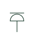
Installation plan mark for a socket outlet that includes a protective earth contact for Class I appliances.

Plan mark for a flush floor box containing power and often data outlets in open-plan floors.
Elora Grid helps electrical teams work with drawings, specifications and equipment information. Explore the drafting workflow or join the early-access waitlist.