N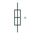
Neutral link, closed
A removable link in the neutral conductor shown in its closed position, allowing the neutral to be opened for testing.
IEC
A neutral link drawn removed or open, showing the neutral conductor disconnected at that point.
In plain English
The open neutral link shows the link withdrawn so that the neutral is disconnected. Drawings use it where a circuit is normally run with the neutral open, for example to isolate a spare or to segregate a neutral during a changeover, and on test procedures that show the link removed.
An open neutral on a live four-wire circuit can cause severe overvoltage on single-phase loads, so an open link in normal service needs a clear reason on the drawing. The symbol says nothing about the phase conductors, which may still be supplied with operating power.
Ask why the neutral is shown open in service. Check that phases are also isolated before working. An open neutral link is disconnected; the closed form shows normal continuity.
A neutral link drawn removed or open, showing the neutral conductor disconnected at that point. An open neutral link is disconnected; the closed form shows normal continuity.
Read the source: Fuse and neutral-link symbols · Definition of standardised earthing schemes
Autodesk IEC-60617 Symbol Preview: Fuses (Neutral Link - Open); vendor family reference, not certified IEC geometry.
Shown as an independently authored educational illustration. Use the cited publication and drawing legend to verify the required drafting form.
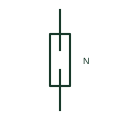
The open neutral link shows the link withdrawn so that the neutral is disconnected. Drawings use it where a circuit is normally run with the neutral open, for example to isolate a spare or to segregate a neutral during a changeover, and on test procedures that show the link removed.
An open neutral on a live four-wire circuit can cause severe overvoltage on single-phase loads, so an open link in normal service needs a clear reason on the drawing. The symbol says nothing about the phase conductors, which may still be energised.
An open neutral link is disconnected; the closed form shows normal continuity.
These public references support the explanation and provide further detail. Their graphics and downloadable files remain with their publishers.
Public IEC-oriented preview listing neutral link closed and open forms.
Public installation-guide definitions of the neutral's role in earthing schemes.
This illustration was authored independently by Elora Grid to explain the concept. It is not reproduced from a customer drawing, an official standard graphic or a manufacturer CAD file. Its correspondence to an exact IEC or IEEE symbol identifier has not been certified.
SVG and DXF downloads contain this original artwork. DXF uses unscaled drawing units; a GA envelope supplies no product dimensions, clearances or fabrication information. Original artwork is available under CC BY 4.0. Third-party references retain their own terms.
A removable link in the neutral conductor shown in its closed position, allowing the neutral to be opened for testing.
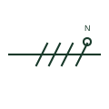
A mark on a single-line conductor group identifying which conductor is the neutral, often drawn as a small circle on a stroke.
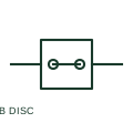
A disconnect terminal includes a documented separable path for circuit isolation or testing at the wiring level.
Elora Grid helps electrical teams work with drawings, specifications and equipment information. Explore the drafting workflow or join the early-access waitlist.