XOR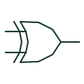
Exclusive-OR gate
For two positive-logic inputs, produces a true output when the input states differ.
Schematic
Rectangular element marked =1: the output is active when one and only one input is active.
In plain English
The =1 additional drawing mark defines an exclusive-OR in the strict IEC sense: exactly one input must be active for the output to be active. For a two-input element this matches the familiar XOR truth table. For more than two inputs it is not the same as a cascaded parity function, which IEC writes as 2k+1.
On control drawings the =1 element appears in discrepancy checks, such as comparing a commanded position with a feedback contact, and in change-detection logic. The drafter should keep the element at two inputs unless the one-and-only-one meaning is truly intended.
The additional drawing mark does not indicate timing tolerance. Discrepancy logic normally needs a delay element after the =1 box so that the alarm ignores normal transit time; that delay is a separate symbol.
Rectangular element marked =1: the output is active when one and only one input is active. The 2k+1 odd-parity element gives the same result for two inputs but a different result for three or more.
Read the source: Overview of IEEE Standard 91-1984: explanation of logic symbols (SDYZ001A) · SN74HC86 — XOR gate logic
Qualifying-symbol and dependency conventions as explained in TI's public overview of IEEE Std 91-1984, which incorporates IEC 617-12 work. Independent educational drawing; not certified IEC geometry or an IEC database identifier. The counterpart is the matching functional concept; no equivalence of every detailed standard graphic is asserted.
Shown as an independently authored educational illustration. Use the cited publication and drawing legend to verify the required drafting form.
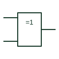
The =1 qualifier defines an exclusive-OR in the strict IEC sense: exactly one input must be active for the output to be active. For a two-input element this matches the familiar XOR truth table. For more than two inputs it is not the same as a cascaded parity function, which IEC writes as 2k+1.
On control drawings the =1 element appears in discrepancy checks, such as comparing a commanded position with a feedback contact, and in change-detection logic. The drafter should keep the element at two inputs unless the one-and-only-one meaning is truly intended.
The qualifier does not indicate timing tolerance. Discrepancy logic normally needs a delay element after the =1 box so that the alarm ignores normal transit time; that delay is a separate symbol.
The 2k+1 odd-parity element gives the same result for two inputs but a different result for three or more.
These public references support the explanation and provide further detail. Their graphics and downloadable files remain with their publishers.
Defines =1 and distinguishes it from the 2k+1 parity qualifier.
Manufacturer exclusive-OR documentation.
This illustration was authored independently by Elora Grid to explain the concept. It is not reproduced from a customer drawing, an official standard graphic or a manufacturer CAD file. Its correspondence to an exact IEC or IEEE symbol identifier has not been certified.
SVG and DXF downloads contain this original artwork. DXF uses unscaled drawing units; a GA envelope supplies no product dimensions, clearances or fabrication information. Original artwork is available under CC BY 4.0. Third-party references retain their own terms.
For two positive-logic inputs, produces a true output when the input states differ.
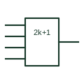
Element marked 2k+1 that is active when an odd number of inputs are active, as used for parity.
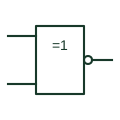
IEC =1 box with a negated output, giving the two-input equivalence or exclusive-NOR function.
Elora Grid helps electrical teams work with drawings, specifications and equipment information. Explore the drafting workflow or join the early-access waitlist.