X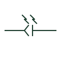
Fibre-optic connector
A demountable joint between optical fibres, drawn as a connector on a fibre link with an optical path mark.
IEC
A cable line carrying light rather than current, used for protection signalling, SCADA links and substation process bus.
In plain English
The optical fibre cable representation marks a link that carries light signals. In power systems it is used for line differential protection signalling, IEC 61850 station and process bus networks, and links between buildings where electrical separation without a direct conducting path avoids earth potential rise problems. It is commonly drawn with a distinct line style or a small light-path mark on the conductor.
Because the fibre carries no current, it must never be read as a power or earth path. The drawing should still give the fibre count, fibre type (single mode or multimode) and connector types at each end. Spare fibres and splice points are tracked in a fibre schedule rather than on the schematic.
Do not treat the fibre as an electrical path for earthing or interlocking. Check fibre type and count against the equipment ports. An optical fibre cable carries light and gives electrical separation without a direct conducting path; a coaxial cable carries electrical signals and can transfer earth potential.
A cable line carrying light rather than current, used for protection signalling, SCADA links and substation process bus. An optical fibre cable carries light and gives electrical separation without a direct conducting path; a coaxial cable carries electrical signals and can transfer earth potential.
Read the source: IEC-60617 symbol preview directory · IEEE/ANSI 315-1975: graphic symbols for electrical and electronics diagrams
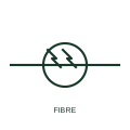
The optical fibre cable representation marks a link that carries light signals. In power systems it is used for line differential protection signalling, IEC 61850 station and process bus networks, and links between buildings where galvanic isolation avoids earth potential rise problems. It is commonly drawn with a distinct line style or a small light-path mark on the conductor.
Because the fibre carries no current, it must never be read as a power or earth path. The drawing should still give the fibre count, fibre type (single mode or multimode) and connector types at each end. Spare fibres and splice points are tracked in a fibre schedule rather than on the schematic.
An optical fibre cable carries light and gives galvanic isolation; a coaxial cable carries electrical signals and can transfer earth potential.
These public references support the explanation and provide further detail. Their graphics and downloadable files remain with their publishers.
Public directory of IEC-oriented symbol families.
Standards context for transmission-path graphics.
This illustration was authored independently by Elora Grid to explain the concept. It is not reproduced from a customer drawing, an official standard graphic or a manufacturer CAD file. Its correspondence to an exact IEC or IEEE symbol identifier has not been certified.
SVG and DXF downloads contain this original artwork. DXF uses unscaled drawing units; a GA envelope supplies no product dimensions, clearances or fabrication information. Original artwork is available under CC BY 4.0. Third-party references retain their own terms.
A demountable joint between optical fibres, drawn as a connector on a fibre link with an optical path mark.
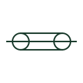
A centre conductor drawn within a concentric outer conductor, used for RF, video and some high-frequency measurement leads.
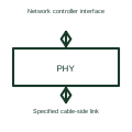
An Ethernet PHY handles the electrical signalling of the selected Ethernet physical link.
Elora Grid helps electrical teams work with drawings, specifications and equipment information. Explore the drafting workflow or join the early-access waitlist.