GRID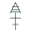
Utility grid connection
The symbol for the external utility network as a supply source at the top of a single-line diagram.
SLD
A marker on a single-line diagram identifying where a customer installation or microgrid meets the public network.
In plain English
The point of common coupling is the location on the network nearest to the installation where other customers are, or could be, connected. Harmonic, flicker and voltage limits in connection agreements are assessed at this point, and microgrid islanding decisions are often defined relative to it.
Drawings mark the point with a dot, circle, flag or label PCC on the busbar or cable, often together with the ownership boundary and the revenue meter. A microgrid may show both a PCC with the utility and internal points of connection for each source.
The marker carries no electrical function itself. It does not tell you the ownership boundary, which can differ from the PCC, or the fault level at that point, which must be stated for compliance assessments.
A marker on a single-line diagram identifying where a customer installation or microgrid meets the public network. A PCC marks an assessment point; a utility grid connection symbol represents the supply itself.
Read the source: Electrical installation design methodology and references · Reliable hybrid power and microgrid solutions
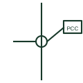
The point of common coupling is the location on the network nearest to the installation where other customers are, or could be, connected. Harmonic, flicker and voltage limits in connection agreements are assessed at this point, and microgrid islanding decisions are often defined relative to it.
Drawings mark the point with a dot, circle, flag or label PCC on the busbar or cable, often together with the ownership boundary and the revenue meter. A microgrid may show both a PCC with the utility and internal points of connection for each source.
The marker carries no electrical function itself. It does not tell you the ownership boundary, which can differ from the PCC, or the fault level at that point, which must be stated for compliance assessments.
A PCC marks an assessment point; a utility grid connection symbol represents the supply itself.
These public references support the explanation and provide further detail. Their graphics and downloadable files remain with their publishers.
Public electrical installation design references covering supply connection.
Public microgrid context with mains import and export at the connection point.
This illustration was authored independently by Elora Grid to explain the concept. It is not reproduced from a customer drawing, an official standard graphic or a manufacturer CAD file. Its correspondence to an exact IEC or IEEE symbol identifier has not been certified.
SVG and DXF downloads contain this original artwork. DXF uses unscaled drawing units; a GA envelope supplies no product dimensions, clearances or fabrication information. Original artwork is available under CC BY 4.0. Third-party references retain their own terms.
The symbol for the external utility network as a supply source at the top of a single-line diagram.
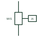
The switching device that separates a microgrid from the utility for islanding and reconnects it after synchronising.
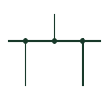
A common conductive connection distributing power to connected circuits.
Elora Grid helps electrical teams work with drawings, specifications and equipment information. Explore the drafting workflow or join the early-access waitlist.