BUS-TR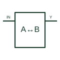
Logic bus transceiver
Drives data between two digital buses according to the selected direction and enable conditions.
Schematic
In plain English
An RS-422 interface uses differential signalling for its selected serial connection.
A controller can communicate through a suitable differential driver and receiver arrangement.
Identify the driver and receiver ends of the intended differential connection. Do not copy an RS-485 multi-driver bus arrangement just because both names refer to differential interfaces. The chosen parts and network design establish the permitted connections and direction of information flow.
Not automatically. Driver arrangements, permitted connections and device characteristics differ. Confirm the complete link rather than treating the interface names as equivalent wiring instructions.
Read the source: RS-485 and RS-422 interfaces
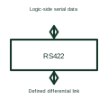
An RS-422 label does not automatically imply an RS-485 multi-driver bus arrangement.
These public references support the explanation and provide further detail. Their graphics and downloadable files remain with their publishers.
RS-485 and RS-422 interfaces: public technical context for the named function. Product and compliance details remain with the publisher.
This illustration was authored independently by Elora Grid to explain the concept. It is not reproduced from a customer drawing, an official standard graphic or a manufacturer CAD file. Its correspondence to an exact IEC or IEEE symbol identifier has not been certified.
SVG and DXF downloads contain this original artwork. DXF uses unscaled drawing units; a GA envelope supplies no product dimensions, clearances or fabrication information. Original artwork is available under CC BY 4.0. Third-party references retain their own terms.
Drives data between two digital buses according to the selected direction and enable conditions.
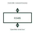
An RS-485 transceiver sends and receives differential serial signals on its specified bus arrangement.
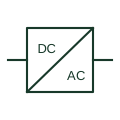
An identified interface converting electrical power between documented circuit forms.

An identified electrical connection point linking schematic and wiring information.
Elora Grid helps electrical teams work with drawings, specifications and equipment information. Explore the drafting workflow or join the early-access waitlist.