TB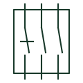
Relay test block
Multi-pole test facility between CT, VT and trip wiring and a relay, allowing safe isolation and test injection.
Schematic
Plug inserted into a test block or switch to connect test equipment to the relay side while isolating the plant side.
In plain English
A test plug fits into a test block or test switch and brings each pole out to test leads. Depending on its design it can connect test equipment to the relay side only, or link plant and relay sides through an ammeter for in-service current measurement.
Different plug types for the same block do different things, so the procedure must name the plug variant. The symbol shows the plug's poles but not its internal links, and using the wrong plug can open a live CT circuit or leave a trip output connected.
Check which plug variant the procedure requires. Read the internal links of each pole. A test plug is the removable part; the test block or switch is the fixed part wired into the circuit.
Plug inserted into a test block or switch to connect test equipment to the relay side while isolating the plant side. A test plug is the removable part; the test block or switch is the fixed part wired into the circuit.
Read the source: Transformer terminals for measuring and test circuits
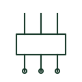
A test plug fits into a test block or test switch and brings each pole out to test leads. Depending on its design it can connect test equipment to the relay side only, or link plant and relay sides through an ammeter for in-service current measurement.
Different plug types for the same block do different things, so the procedure must name the plug variant. The symbol shows the plug's poles but not its internal links, and using the wrong plug can open a live CT circuit or leave a trip output connected.
A test plug is the removable part; the test block or switch is the fixed part wired into the circuit.
These public references support the explanation and provide further detail. Their graphics and downloadable files remain with their publishers.
Public manufacturer range of transformer and test terminals for measuring and protection circuits.
This illustration was authored independently by Elora Grid to explain the concept. It is not reproduced from a customer drawing, an official standard graphic or a manufacturer CAD file. Its correspondence to an exact IEC or IEEE symbol identifier has not been certified.
SVG and DXF downloads contain this original artwork. DXF uses unscaled drawing units; a GA envelope supplies no product dimensions, clearances or fabrication information. Original artwork is available under CC BY 4.0. Third-party references retain their own terms.
Multi-pole test facility between CT, VT and trip wiring and a relay, allowing safe isolation and test injection.
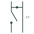
Panel test switch for CT circuits that shorts the CT side before opening the relay side, with a test jack between.
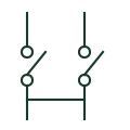
A current-transformer terminal arrangement providing documented test and shorting facilities.
Elora Grid helps electrical teams work with drawings, specifications and equipment information. Explore the drafting workflow or join the early-access waitlist.