G 3PH SYNC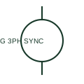
Three-phase synchronous generator
A three-phase synchronous generator supplies a documented AC source associated with its mechanical prime mover and excitation system.
SLD / Schematic
A squirrel-cage asynchronous machine driven above synchronous speed so that it delivers power into a three-phase network.
In plain English
An induction generator is an asynchronous machine driven slightly faster than synchronous speed by a turbine or engine. It exports active power but needs reactive power from the network or from capacitors to establish its magnetic field, so it cannot normally hold voltage and frequency on its own.
The symbol is a machine circle with G, a three-phase AC mark and often the letters ASG or a squirrel-cage indication to separate it from a synchronous generator. It is found in small hydro, older wind turbines and some biogas or heat recovery sets connected in parallel with a stronger supply.
The symbol does not tell you whether the machine can run isolated with self-excitation capacitors, or what happens to its output when the network trips. Islanded operation and reverse power or loss-of-mains protection have to be read from the protection and control drawings.
A squirrel-cage asynchronous machine driven above synchronous speed so that it delivers power into a three-phase network. An induction generator draws its magnetising current from the network; a synchronous generator has its own field and can regulate voltage.
Read the source: Three-phase motor symbol variants · IEEE/ANSI 315-1975: graphic symbols for electrical and electronics diagrams
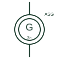
An induction generator is an asynchronous machine driven slightly faster than synchronous speed by a turbine or engine. It exports active power but needs reactive power from the network or from capacitors to establish its magnetic field, so it cannot normally hold voltage and frequency on its own.
The symbol is a machine circle with G, a three-phase AC mark and often the letters ASG or a squirrel-cage indication to separate it from a synchronous generator. It is found in small hydro, older wind turbines and some biogas or heat recovery sets connected in parallel with a stronger supply.
The symbol does not tell you whether the machine can run isolated with self-excitation capacitors, or what happens to its output when the network trips. Islanded operation and reverse power or loss-of-mains protection have to be read from the protection and control drawings.
An induction generator draws its magnetising current from the network; a synchronous generator has its own field and can regulate voltage.
These public references support the explanation and provide further detail. Their graphics and downloadable files remain with their publishers.
Public three-phase induction machine symbol family; the generator mark is added in this original illustration.
Graphic-symbol standards context for rotating machines.
This illustration was authored independently by Elora Grid to explain the concept. It is not reproduced from a customer drawing, an official standard graphic or a manufacturer CAD file. Its correspondence to an exact IEC or IEEE symbol identifier has not been certified.
SVG and DXF downloads contain this original artwork. DXF uses unscaled drawing units; a GA envelope supplies no product dimensions, clearances or fabrication information. Original artwork is available under CC BY 4.0. Third-party references retain their own terms.
A three-phase synchronous generator supplies a documented AC source associated with its mechanical prime mover and excitation system.
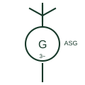
A wind turbine whose squirrel-cage induction generator connects to the network directly, running at nearly constant speed.
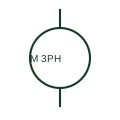
A three-phase AC motor is a load supplied from three documented phases.

An electrical generating source represented in a power-system drawing.
Elora Grid helps electrical teams work with drawings, specifications and equipment information. Explore the drafting workflow or join the early-access waitlist.