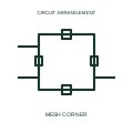
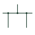
Understand the difference. Compare the meaning, drawing context and source references of two entries. A similar graphic or shared abbreviation does not establish equivalence.
First referenceCurrent transformer · CT Voltage transformer · VT / PT Circuit breaker · CB Disconnector · Isolator Load-break switch · LBS Earthing switch · ES Fuse · FU Busbar · Bus Normally open contact · NO Normally closed contact · NC Changeover contact · CO Relay coil · Coil Contactor · KM Normally open pushbutton · PB NO Normally closed pushbutton · PB NC Emergency-stop operator · E-stop Selector switch · SS Indicator lamp · Lamp Terminal connection · Terminal CT test terminal · CT test Power transformer · TX Generator · GEN Three-phase motor · M PLC input / output · PLC I/O Capacitor · C Resistor · R Protective earth · PE Battery · BAT Power converter / inverter · PCS Single-pole circuit breaker · CB 1P Thermal circuit breaker · CB TH Thermal-magnetic circuit breaker · CB TM Current-limiting circuit breaker · CB LIM Residual-current circuit breaker · RCCB Residual-current breaker with overcurrent protection · RCBO Circuit breaker with undervoltage release · CB UV Circuit breaker with electronic trip unit · CB ETU Miniature circuit breaker · MCB Moulded-case circuit breaker · MCCB Air circuit breaker · ACB Additional circuit-breaker pole · CB POLE Switch-disconnector · SD Lockable disconnector · DS LOCK Lockable switch-disconnector · SD LOCK Three-position disconnector · DS 3POS Semiconductor power switch · SSW Unidirectional semiconductor power switch · SSW UNI Two-pole power switch · SW 2P Disconnector auxiliary NO contact · DS AUX NO Disconnector auxiliary NC contact · DS AUX NC Fused switch · SW FUSE Fuse-switch · FUSE SW Additional fused-switch pole · FUSE POLE General-purpose full-range fuse · gG Motor short-circuit fuse · aM Motor full-range fuse · gM Current transformer with two secondaries · CT 2SEC Tapped-secondary current transformer · CT TAP Current transformer with primary conductor indication · CT PRI Core-balance current transformer · CBCT Residual connection of phase CTs · CT RES Single-phase two-winding transformer · TX 1PH Electrostatically screened transformer · TX SCREEN Three-winding transformer · TX 3W Adjustable-ratio transformer · TX ADJ Single-phase autotransformer · AT 1PH Three-phase star autotransformer · AT 3PH Y Star-delta transformer · TX Y-D Delta-star transformer · TX D-Y Delta-delta transformer · TX D-D Star-star transformer · TX Y-Y Star-zigzag transformer · TX Y-Z Star-star-delta three-winding transformer · TX Y-Y-D Delta winding connection · DELTA Open-delta winding connection · OPEN D Star winding connection · STAR Y Star winding with accessible neutral · Y N Zigzag winding connection · ZIGZAG Mechanically latched relay coil · K LATCH Relay reset coil · K RESET Solid-state relay · SSR Polarised relay coil · K POL AC relay coil · K AC High-speed relay · K FAST Measuring relay · K MEAS Relay coil with diode suppression · K DIODE Relay coil with diode and LED · K D LED Relay coil with capacitor suppression · K CAP Relay coil with RC suppression · K RC Counter relay with manual reset · COUNT MAN Counter relay with electrical reset · COUNT ELEC Non-resettable counter relay · COUNT TOTAL On-delay timer relay · TON Off-delay timer relay · TOFF On-delay normally-open contact · TON NO On-delay normally-closed contact · TON NC Off-delay normally-open contact · TOFF NO Off-delay normally-closed contact · TOFF NC Maintained normally-open contact · NO HOLD Maintained normally-closed contact · NC HOLD Manually unlatched NO contact · NO UNLATCH Manually unlatched NC contact · NC UNLATCH Early-make normally-open contact · NO EARLY Late-make normally-open contact · NO LATE Early-break normally-closed contact · NC EARLY Late-break normally-closed contact · NC LATE Make-before-break changeover contact · MBB Motor overload trip NC contact · OL NC Motor overload alarm NO contact · OL NO Illuminated normally-open pushbutton · PB NO LAMP Illuminated normally-closed pushbutton · PB NC LAMP Maintained normally-open pushbutton · PB NO HOLD Maintained normally-closed pushbutton · PB NC HOLD Key-operated normally-open switch · KEY NO Key-operated normally-closed switch · KEY NC Latched key-operated switch · KEY HOLD Pull-cord switch · PULL CORD Foot-operated switch · FOOT Lever-operated switch · LEVER Three-position maintained selector · SEL 3 HOLD Three-position selector returning from left · SEL 3 LRET Three-position selector returning from right · SEL 3 RRET Three-position centre-return selector · SEL 3 CRET Three-position key selector · KEY SEL 3 Four-position maintained selector · SEL 4 HOLD Four-position key selector · KEY SEL 4 Normally-open limit switch · LS NO Normally-closed limit switch · LS NC Roller-operated limit switch · LS ROLLER Cam-operated limit switch · LS CAM Pressure switch NO · PS NO Pressure switch NC · PS NC Temperature switch NO · TS NO Temperature switch NC · TS NC Self-operating thermal switch · TS SELF Float level switch NO · LS FLOAT NO Float level switch NC · LS FLOAT NC Liquid flow switch · FS LIQ Gas flow switch · FS GAS Inductive proximity switch · PROX IND Three-wire inductive proximity switch · PROX IND 3W Capacitive proximity switch · PROX CAP Magnetic proximity switch · PROX MAG Photoelectric emitter-receiver switch · PHOTO Thermocouple · TC Resistance temperature detector · RTD Voltmeter · V Ammeter · A Power-factor meter · PF Phase-angle meter · PHASE Frequency meter · Hz Temperature indicator · TEMP Tachometer · RPM Running-hours meter · HOURS Ampere-hour meter · Ah Recording wattmeter · W REC Reactive-power meter · var Synchronoscope · SYNC SCOPE Active-power indicator · kW Differential voltmeter · DELTA V Active-energy meter · kWh Reactive-energy meter · kvarh Maximum-current monitoring relay · I HIGH Minimum-current monitoring relay · I LOW Current window monitoring relay · I WINDOW Differential-current measuring relay · I DIFF Residual-voltage monitoring relay · U RES Loss-of-voltage monitoring relay · U LOSS Phase-loss monitoring relay · PH LOSS Frequency monitoring relay · f MON Minimum active-power relay · P LOW Feed-through terminal block · TB FEED Disconnect terminal block · TB DISC Knife-disconnect terminal · TB KNIFE Fuse terminal block · TB FUSE Diode terminal block · TB DIODE Component terminal block · TB COMP Multilevel terminal block · TB LEVEL Multi-conductor terminal block · TB MULTI Protective-earth terminal block · TB PE Sensor terminal block · TB SENSOR Actuator terminal block · TB ACT Plug-in terminal block · TB PLUG High-current terminal block · TB POWER Terminal jumper bridge · TB BRIDGE Plug and socket connector pair · PLUG SOCKET Connector plug half · PLUG Connector socket half · SOCKET Wire splice · SPLICE Earth connection · EARTH Functional earth · FE Protective equipotential bonding · BOND PE Functional equipotential bonding · BOND FE Surge arrester · SA Gas-discharge protection tube · GDT Spark-gap protective element · SPARK GAP Variable resistor · R VAR Potentiometer · POT Light-dependent resistor · LDR Heating element · HEATER RC network · RC Varistor · VDR Current-measuring shunt · SHUNT Electrolytic capacitor · C ELEC Feedthrough capacitor · C FEED Adjustable capacitor · C ADJ Three-phase power-factor capacitor · CAP 3PH Reactor · L Iron-core reactor · L IRON Gapped-core inductor · L GAP Adjustable-core inductor · L ADJ Diode · D Photodiode · PD Zener diode · ZD DIAC · DIAC Single-phase bridge rectifier · BR 1PH Three-phase bridge rectifier · BR 3PH Silicon-controlled rectifier · SCR Gate-turn-off thyristor · GTO TRIAC · TRIAC Bidirectional breakdown diode · TVS BI Single-phase AC motor · M 1PH AC Single-phase motor with fan · M 1PH FAN Three-phase AC motor · M 3PH Three-phase motor with fan · M 3PH FAN Wound-rotor induction motor · M WR Three-phase synchronous motor · M 3PH SYNC DC motor · M DC Permanent-magnet DC motor · M DC PM Series-excited DC motor · M DC SERIES Separately excited DC motor · M DC SEP DC generator · G DC Compound-excited DC generator · G DC COMP Three-phase synchronous generator · G 3PH SYNC Permanent-magnet synchronous generator · G 3PH PM AC-to-DC power supply · PSU AC-DC DC-to-DC converter · DC-DC DC-to-AC inverter · INV DC-AC DC uninterruptible power supply · UPS DC AC uninterruptible power supply · UPS AC Capacitor buffer module · BUFFER CAP Redundant power-supply decoupling module · PSU RED Analog current signal isolator · ISO I-I Temperature measuring transducer · TEMP TX Photovoltaic inverter · PV INV Single-phase AC source · AC 1PH Three-phase AC source · AC 3PH Photovoltaic generator · PV GEN Solar generating station · SOLAR STN Wind generating station · WIND STN Substation · SUBSTATION Converter substation · CONV STN Generic electrical load · LOAD Transformer-fed indicator lamp · LAMP TX Push-to-test indicator lamp · LAMP TEST LED indicator lamp · LAMP LED Flashing indicator lamp · LAMP FLASH Flashing beacon · BEACON FLASH Rotating beacon · BEACON ROT PLC digital input · DI PLC relay output · DO RELAY PLC transistor output · DO TRANS PLC analog input · AI PLC analog output · AO PLC temperature input · TI Capacitor voltage transformer · CVT / CCVT ANSI/IEEE circuit breaker symbol · CB ANSI/IEEE thermal circuit breaker symbol · CB TH ANSI/IEEE thermal-magnetic circuit breaker symbol · CB TM ANSI/IEEE current-limiting circuit breaker symbol · CB LIM ANSI/IEEE circuit breaker with undervoltage release symbol · CB UV ANSI/IEEE circuit breaker with electronic trip unit symbol · CB ETU ANSI/IEEE disconnector symbol · Isolator ANSI/IEEE switch-disconnector symbol · SD ANSI/IEEE lockable disconnector symbol · DS LOCK ANSI/IEEE lockable switch-disconnector symbol · SD LOCK ANSI/IEEE fused switch symbol · SW FUSE ANSI/IEEE fuse symbol · FU ANSI/IEEE fuse-switch symbol · FUSE SW ANSI/IEEE current transformer symbol · CT ANSI/IEEE current transformer with two secondaries symbol · CT 2SEC ANSI/IEEE tapped-secondary current transformer symbol · CT TAP ANSI/IEEE voltage transformer symbol · VT / PT ANSI/IEEE power transformer symbol · TX ANSI/IEEE electrostatically screened transformer symbol · TX SCREEN ANSI/IEEE three-winding transformer symbol · TX 3W ANSI/IEEE adjustable-ratio transformer symbol · TX ADJ ANSI/IEEE single-phase autotransformer symbol · AT 1PH ANSI/IEEE reactor symbol · L ANSI/IEEE iron-core reactor symbol · L IRON ANSI/IEEE gapped-core inductor symbol · L GAP ANSI/IEEE adjustable-core inductor symbol · L ADJ ANSI/IEEE normally open contact symbol · NO ANSI/IEEE normally closed contact symbol · NC ANSI/IEEE changeover contact symbol · CO ANSI/IEEE relay coil symbol · Coil ANSI/IEEE mechanically latched relay coil symbol · K LATCH ANSI/IEEE relay reset coil symbol · K RESET ANSI/IEEE polarised relay coil symbol · K POL ANSI/IEEE ac relay coil symbol · K AC ANSI/IEEE relay coil with diode suppression symbol · K DIODE ANSI/IEEE relay coil with rc suppression symbol · K RC ANSI/IEEE on-delay timer relay symbol · TON ANSI/IEEE off-delay timer relay symbol · TOFF ANSI/IEEE maintained normally-open contact symbol · NO HOLD ANSI/IEEE maintained normally-closed contact symbol · NC HOLD ANSI/IEEE early-make normally-open contact symbol · NO EARLY ANSI/IEEE late-make normally-open contact symbol · NO LATE ANSI/IEEE early-break normally-closed contact symbol · NC EARLY ANSI/IEEE late-break normally-closed contact symbol · NC LATE ANSI/IEEE motor overload trip nc contact symbol · OL NC ANSI/IEEE motor overload alarm no contact symbol · OL NO ANSI/IEEE normally open pushbutton symbol · PB NO ANSI/IEEE normally closed pushbutton symbol · PB NC ANSI/IEEE illuminated normally-open pushbutton symbol · PB NO LAMP ANSI/IEEE illuminated normally-closed pushbutton symbol · PB NC LAMP ANSI/IEEE maintained normally-open pushbutton symbol · PB NO HOLD ANSI/IEEE maintained normally-closed pushbutton symbol · PB NC HOLD ANSI/IEEE selector switch symbol · SS ANSI/IEEE three-position maintained selector symbol · SEL 3 HOLD ANSI/IEEE three-position centre-return selector symbol · SEL 3 CRET ANSI/IEEE three-position key selector symbol · KEY SEL 3 ANSI/IEEE four-position maintained selector symbol · SEL 4 HOLD ANSI/IEEE four-position key selector symbol · KEY SEL 4 ANSI/IEEE normally-open limit switch symbol · LS NO ANSI/IEEE normally-closed limit switch symbol · LS NC ANSI/IEEE roller-operated limit switch symbol · LS ROLLER ANSI/IEEE pressure switch no symbol · PS NO ANSI/IEEE pressure switch nc symbol · PS NC ANSI/IEEE temperature switch no symbol · TS NO ANSI/IEEE temperature switch nc symbol · TS NC ANSI/IEEE float level switch no symbol · LS FLOAT NO ANSI/IEEE float level switch nc symbol · LS FLOAT NC ANSI/IEEE liquid flow switch symbol · FS LIQ ANSI/IEEE terminal connection symbol · Terminal ANSI/IEEE numbered terminal symbol · TERM 1 ANSI/IEEE plug and socket connector pair symbol · PLUG SOCKET ANSI/IEEE connector plug half symbol · PLUG ANSI/IEEE connector socket half symbol · SOCKET ANSI/IEEE wire splice symbol · SPLICE ANSI/IEEE protective earth symbol · PE ANSI/IEEE functional earth symbol · FE ANSI/IEEE resistor symbol · R ANSI/IEEE variable resistor symbol · R VAR ANSI/IEEE potentiometer symbol · POT ANSI/IEEE light-dependent resistor symbol · LDR ANSI/IEEE heating element symbol · HEATER ANSI/IEEE varistor symbol · VDR ANSI/IEEE current-measuring shunt symbol · SHUNT ANSI/IEEE capacitor symbol · C ANSI/IEEE electrolytic capacitor symbol · C ELEC ANSI/IEEE feedthrough capacitor symbol · C FEED ANSI/IEEE adjustable capacitor symbol · C ADJ ANSI/IEEE diode symbol · D ANSI/IEEE photodiode symbol · PD ANSI/IEEE zener diode symbol · ZD ANSI/IEEE single-phase bridge rectifier symbol · BR 1PH ANSI/IEEE silicon-controlled rectifier symbol · SCR ANSI/IEEE triac symbol · TRIAC ANSI/IEEE voltmeter symbol · V ANSI/IEEE ammeter symbol · A ANSI/IEEE power-factor meter symbol · PF ANSI/IEEE frequency meter symbol · Hz ANSI/IEEE recording wattmeter symbol · W REC ANSI/IEEE reactive-power meter symbol · var ANSI/IEEE synchronoscope symbol · SYNC SCOPE ANSI/IEEE running-hours meter symbol · HOURS ANSI/IEEE single-phase ac motor symbol · M 1PH AC ANSI/IEEE three-phase ac motor symbol · M 3PH ANSI/IEEE wound-rotor induction motor symbol · M WR ANSI/IEEE dc motor symbol · M DC ANSI/IEEE permanent-magnet dc motor symbol · M DC PM ANSI/IEEE three-phase synchronous generator symbol · G 3PH SYNC ANSI/IEEE dc generator symbol · G DC ANSI/IEEE indicator lamp symbol · Lamp ANSI/IEEE transformer-fed indicator lamp symbol · LAMP TX ANSI/IEEE push-to-test indicator lamp symbol · LAMP TEST ANSI/IEEE led indicator lamp symbol · LAMP LED ANSI/IEEE on-delay normally-open contact symbol · TON NO ANSI/IEEE on-delay normally-closed contact symbol · TON NC ANSI/IEEE off-delay normally-open contact symbol · TOFF NO ANSI/IEEE off-delay normally-closed contact symbol · TOFF NC Positive-operation direction qualifier · Q070109 Manual-operation qualifier · Q021301 Protected-access manual-operation qualifier · Q021302 Pushbutton-operation qualifier · Q021305 Emergency-operation qualifier · Q021308 Rotary-operation qualifier · Q021304 Key-operation qualifier · Q021313 Foot-operation qualifier · Q021310 Lever-operation qualifier · Q021311 Crank-operation qualifier · Q021214 Handwheel-operation qualifier · Q021309 Liquid-level actuation qualifier · Q021401 Event-count actuation qualifier · Q021402 Liquid-flow actuation qualifier · Q021403 Gas-flow actuation qualifier · Q021404 Motor-operation qualifier · Q021326 Timed-operation qualifier · Q021327 Roller-operation qualifier · Q021315 Cam-operation qualifier · Q021316 Cam-profile indication · Q021317 Switch-position function qualifier · Q070106 Isolation-function qualifier · Q070103 Switch-disconnector function qualifier · Q070104 Circuit-breaker function qualifier · Q070102 Power-contactor function qualifier · Q070101 Automatic-trip qualifier · Q070105 Spring-return qualifier · Q070107 Maintained-position qualifier · Q070108 One-way linear-motion qualifier · Q020401R Two-way linear-motion qualifier · Q020402 Transition indication · Q101101 One-way rotary-motion qualifier · Q020403 Two-way rotary-motion qualifier · Q020404 Limited two-way rotary-motion qualifier · Q020405 Unidirectional propagation qualifier · Q020501 Simultaneous bidirectional propagation qualifier · Q020502 Alternating bidirectional propagation qualifier · Q020503 Signal-transmission qualifier · Q020504 Signal-reception qualifier · Q020505 Outbound-energy-flow qualifier · Q020506 Inbound-energy-flow qualifier · Q020507 Bidirectional-energy-flow qualifier · Q020508 Thermal-effect qualifier · Q020801 Magnetic-effect qualifier · Q020802 Magnetostrictive-effect qualifier · Q020803 Magnetic-field-effect qualifier · Q020804 Non-ionising radiation qualifier · Q020901 Ionising-radiation qualifier · Q020903 Presumed-fault-location indication · Q021701 Insulation-failure indication · Q021702 Two-phase winding connection · Q060201 Partial-V winding connection · Q060202 Four-phase winding with accessible connection · Q060203 Three-phase T winding connection · Q060204 Six-phase double-delta winding connection · Q060210 Six-phase polygon winding connection · Q060211 Six-phase star winding connection · Q060212 Six-phase double-zigzag winding connection · Q060213 Direct-current supply qualifier · Q020201 Alternating-current supply qualifier · Q020204 Rectified-current with AC component qualifier · Q020212 Automatic mechanical-return indication · Q021207 Mechanical stop-latch indication · Q021208 Mechanical stop latch in neutral state · Q021209 Mechanical stop latch in engaged state · Q021210 Mechanical interlock between devices · Q021211 Two-way latching device · Q1020603 Manually released latching device · Q1020604 Key-controlled two-way latching device · Q1029603 Mechanical clutch connection · Q021216 Disconnected mechanical coupling · Q021217 Engaged mechanical coupling · Q021218 Mechanical gear connection · Q021223 Thermocouple with terminal board · HTC1LTB Pyrometer indication · HIN1P25 Clock indication · HIN1P29 Minute-pulse clock contact · HIN1P33 Pressure-to-current converter · HIN1B10 Single-phase AC-to-DC current converter · HIN1G1 Tachometric dynamo · HIN1B11 Impulse tachometric transducer · HIN1B12 Optical tachometric transducer · HIN1B13 Audible bell · HAN1B Audible buzzer · HAN1Z Audible siren · HAN1S Loudspeaker annunciation · HAN1B7 Combined loudspeaker and microphone · HAN1B8 Microphone input · HAN1B9 Solenoid valve actuator · HSV1 Solenoid closing function for an open valve · HSV1Y1 Electromagnetic brake actuator · HSV1Y4 Solenoid-valve NO auxiliary contact · HSV21 Solenoid-valve NC auxiliary contact · HSV22 Ultrasonic proximity switch · HPX1U Ultrasonic NO switching output · HPX11U Ultrasonic NC switching output · HPX12U Three-wire ultrasonic sensor · HPX11U3 Touch-sensitive switch · HPX1TS Touch-switch NO output · HPX11TS Touch-switch NC output · HPX12TS Three-wire touch-sensitive switch · HPX11TS3 Phase-to-phase voltmeter selector · HSW1S90 Phase-to-neutral voltmeter selector · HSW1S91 Combined line and phase voltmeter selector · HSW1S92 Two-network voltage measurement selector · HSW1S93 Three-point current measurement selector · HSW1S94 Four-point current measurement selector · HSW1S95 Latched pull-cord switch · HPC11L Latched foot-operated switch · HFT11L Latched lever-operated switch · HPB11LSL Three-phase motor with four connections · HMO14 Three-phase induction motor with series excitation · HMO1M3 Star-stator wound-rotor motor with rotor starter · HMO1M5 Six-pole asynchronous motor · HMO1M11 Single-phase series-connected AC motor · HMO1M10 Single-phase synchronous motor · HMO1M16 Permanent-magnet linear DC motor · HMO1M14 Permanent-magnet stepping motor · HMO1M15 Shunt-excited DC motor · HMO1M8 Resistor with disconnecting slider · HVR1R5 Carbon-disc variable resistor · HVR1R8 Magnetoresistive element · HVR1S00689 Differential capacitor · HCA1_S00573 Preset-adjustable capacitor · HCA1_S00575 Split adjustable capacitor · HCA1_S00579 Cable identification marker · HW01 Additional cable-core marker · HW02 Twisted-pair indication · HT0_TW Single power receptacle · HCN1RSGL Duplex power receptacle · HCN1RDUP Generic device boundary · HDV1T6 Standalone source cross-reference · HA2S1_REF Standalone destination cross-reference · HA2D1_REF Reference-only wire arrow · HA1X1 One-line connector representation · HC01PJ_1- One-line terminal representation · HT0001_1- One-line cable identification · HW01_1- One-line bus tap · HDV1_BT_1- One-line power receptacle · HC01WR_1- Connector retaining wire identity · HC01PJ Connector changing wire identity · HCN1PJ Terminal carrying wire identification · HT0W02 Terminal with wire-number transition · HT1002 Conductor connection junction · JUNCTION Unconnected conductor crossing · CROSSING Three-phase conductor group · 3~ Dy5 transformer connection reference · Dy5 Dd6 transformer connection reference · Dd6 Yd5 transformer connection reference · Yd5 Yy6 transformer connection reference · Yy6 Yd11 transformer connection reference · Yd11 Dy11 transformer connection reference · Dy11 Dz0 transformer connection reference · Dz0 Yz5 transformer connection reference · Yz5 Dz6 transformer connection reference · Dz6 Yz11 transformer connection reference · Yz11 Schottky diode · SBD Unidirectional TVS diode · TVS Light-emitting diode · LED Varactor diode · VAR PIN diode · PIN NPN bipolar transistor · NPN PNP bipolar transistor · PNP NPN Darlington transistor · NPN-DAR PNP Darlington transistor · PNP-DAR N-channel JFET · N-JFET P-channel JFET · P-JFET N-channel enhancement MOSFET · N-MOS P-channel enhancement MOSFET · P-MOS N-channel depletion MOSFET · N-DMOS Insulated-gate bipolar transistor · IGBT MOSFET body diode · BODY-D GaN enhancement-mode HEMT · E-HEMT Integrated gate-commutated thyristor · IGCT NPN phototransistor · PHOTO-NPN Phototransistor optocoupler · OPTO-TR Photodiode optocoupler · OPTO-PD Phototriac optocoupler · OPTO-TRIAC Photovoltaic MOSFET driver · PV-DRV Capacitive digital isolator · DIG-ISO Isolated gate driver · ISO-GD Low-side gate driver · LS-GD High-side gate driver · HS-GD Bootstrap gate-drive supply · BOOT Ideal-diode controller · IDEAL-D Hot-swap controller · HOT-SWAP Electronic fuse IC · EFUSE Half-bridge power module · HB-MOD Three-phase sixpack power module · 6-PACK AND gate · AND OR gate · OR NAND gate · NAND NOR gate · NOR Exclusive-OR gate · XOR Exclusive-NOR gate · XNOR Logic inverter · NOT Non-inverting logic buffer · BUF Three-state logic buffer · 3STATE Schmitt-trigger inverter · SCHMITT-NOT Schmitt-trigger buffer · SCHMITT Positive-edge D flip-flop · D-FF Negative-edge JK flip-flop · JK-FF Set-reset latch · SR-LATCH Transparent D latch · D-LATCH Serial-in parallel-out register · SIPO Parallel-in serial-out register · PISO Shift register with output latch · SHIFT-LATCH Ripple binary counter · CTR-RIP Synchronous binary counter · CTR-SYNC Decoded decade counter · DECADE Retriggerable monostable · ONE-SHOT Binary decoder / demultiplexer · DEC Priority encoder · ENC-PRI Digital multiplexer · MUX Digital magnitude comparator · MAG-COMP Binary full adder · ADD Logic bus transceiver · BUS-TR Logic voltage-level translator · LEVEL Open-collector buffer · OC-BUF Parity generator / checker · PARITY Phase-locked loop · PLL Voltage-controlled oscillator · VCO Clock generator · CLK-GEN Watchdog timer · WDT Operational amplifier · OP-AMP Voltage comparator · COMP Instrumentation amplifier · INA Difference amplifier · DIFF-AMP Fully differential amplifier · FDA Current-sense amplifier · CSA Isolation amplifier · ISO-AMP Operational transconductance amplifier · OTA Analogue multiplier · MULT Analogue bilateral switch · A-SW Analogue multiplexer · A-MUX Sample-and-hold amplifier · S/H Analogue-to-digital converter · ADC Digital-to-analogue converter · DAC Series voltage reference · VREF-S Shunt voltage reference · VREF-H Precision rectifier · PREC-RECT RMS-to-DC converter · RMS-DC Voltage / frequency converter · V/F Inverting amplifier circuit · INV-AMP Non-inverting amplifier circuit · NI-AMP Op-amp integrator · INTEGRATOR Op-amp differentiator · DIFFERENTIATOR Active low-pass filter · LPF Active high-pass filter · HPF Active band-pass filter · BPF Active notch filter · NOTCH Transimpedance amplifier · TIA Buck converter topology · BUCK Boost converter topology · BOOST Inverting buck-boost topology · INV-BB Four-switch buck-boost topology · 4SW-BB SEPIC converter topology · SEPIC Cuk converter topology · CUK Zeta converter topology · ZETA Flyback converter topology · FLYBACK Forward converter topology · FORWARD Active-clamp forward topology · ACF Push-pull converter topology · PUSH-PULL Half-bridge DC converter topology · HB-DC Full-bridge DC converter topology · FB-DC Phase-shifted full-bridge topology · PSFB LLC resonant converter topology · LLC Dual-active-bridge topology · DAB Single-phase voltage-source inverter · 1PH-VSI Three-phase voltage-source inverter · 3PH-VSI Neutral-point-clamped inverter · NPC Active front-end rectifier · AFE Battery fuel gauge · SoC Battery charger controller · CHG Battery protection controller · BPROT Battery cell voltage monitor · CELL V Passive battery cell balancer · BAL R Active battery cell balancer · BAL X Battery cell temperature monitor · CELL T Battery pack monitor · PACK Battery precharge circuit · PRE Battery insulation monitoring function · IMD Battery pack current measurement · PACK I AC electric vehicle charge point · AC EV EV control pilot interface · CP EV charging residual-current detection · RCD EV EV charging contactor control · EV K DC electric vehicle charging station · DC EV Bidirectional EV charging interface · V2G EV charger power module · EV PWR EV charging energy measurement · EV kWh Photovoltaic module · PV MOD Photovoltaic string · PV STR Photovoltaic string combiner · COMB MPPT solar charge controller · MPPT Photovoltaic power optimiser · PV OPT Photovoltaic rapid shutdown function · RSD Photovoltaic arc-fault detection · PV AFD CAN bus transceiver · CAN CAN FD transceiver · CAN FD LIN bus transceiver · LIN RS-485 transceiver · RS485 RS-422 interface · RS422 RS-232 transceiver · RS232 Ethernet physical-layer transceiver · PHY Single-pair Ethernet interface · SPE PoE powered-device interface · PoE PD PoE power-sourcing interface · PoE PSE I2C bus buffer · I2C BUF I2C voltage-level translator · I2C LVL SPI interface buffer · SPI BUF LVDS line driver · LVDS TX LVDS line receiver · LVDS RX Magnetic digital isolator · ISO MAG Isolated comparator · ISO CMP Isolated CAN transceiver · ISO CAN Isolated RS-485 transceiver · ISO 485 Isolated I2C interface · ISO I2C Isolated analogue-to-digital converter · ISO ADC Power-source multiplexer · PWR MUX Reverse-polarity protection controller · REV POL Integrated load switch · LOAD SW Smart high-side switch · HS SW Low-side power switch · LS SW Linear voltage regulator · LIN REG Low-dropout voltage regulator · LDO Supply voltage supervisor · SVS Power-good indication · PG Window voltage supervisor · V WIN Power-rail sequencer · SEQ Power-rail enable interface · EN Hall-effect current sensor · HALL I Magnetic position sensor · MAG POS Inductive position sensor · IND POS Ultrasonic distance sensor · US DIST Radar level sensing function · RAD LVL Pressure measurement interface · P MEAS Capacitive level sensor · CAP LVL Relative humidity sensor · RH Flexible conductor · W Screened conductor · W Screened multi-conductor cable · W Screened conductor with earthed screen · W Screened twisted pair · W Coaxial cable · W Coaxial cable with earthed outer conductor · W Conductor in conduit · W Overhead line · OHL Underground cable · UGC Underwater cable · SC Optical fibre cable · OF Conductors within one cable · W Conductor count by numeral · n Neutral conductor mark · N Protective conductor mark · PE PEN conductor mark · PEN Three-phase circuit with neutral and PE marking · 3/N/PE Interchange of conductors · X Conductor branching from a group · W T-connection without junction dot · - Double junction of conductors · - ANSI/IEEE conductor junction symbol · - ANSI/IEEE crossing conductor hop symbol · - ANSI/IEEE shielded conductor symbol · W ANSI/IEEE coaxial cable symbol · W ANSI/IEEE twisted pair symbol · TW ANSI/IEEE multi-conductor cable symbol · W Single-core cable sealing end · SE Multicore cable sealing end · SE Cable straight-through joint · J Cable branch joint · J Cable transition joint · J Separable cable connector · X Sealed cable end · W ANSI/IEEE cable pothead symbol · PH Feeder busway · BD Plug-in busway · BD Busway tap-off connection · TO Busway end feed unit · EF Power distribution block · X Multi-pole plug and socket · X Coaxial plug and socket · X Fibre-optic connector · X Inline cable coupler · X Connector with protective earth contact · X Plug and jack with common pin number · X Additional connector pin · X ANSI/IEEE coaxial connector symbol · J Neutral link, closed · N Neutral link, open · N Bolted connecting link, closed · X Bolted connecting link, open · X Removable earth test link · E Neutral-to-earth link · MEN ANSI/IEEE terminal jumper symbol · JMP ANSI/IEEE main bonding jumper symbol · MBJ Flexible bonding strap · BS Frame or chassis connection · - ANSI/IEEE chassis ground symbol · - Noiseless earth · - Earth electrode · E Earth grid conductor · EG Earth electrode with inspection pit · E Lightning protection down-conductor · DC Lightning air termination · AT Lightning protection test joint · TJ Main earthing terminal · MET ANSI/IEEE earth connection symbol · - ANSI/IEEE protective equipotential bonding symbol · - ANSI/IEEE functional equipotential bonding symbol · - Direct neutral earthing connection · - Cable screen cross-bonding · CB ANSI/IEEE surge arrester symbol · SA ANSI/IEEE spark gap symbol · SG ANSI/IEEE gas discharge tube symbol · GDT Double spark gap · F Symmetric gas discharge tube · F ANSI/IEEE terminal with wire number symbol · TB ANSI/IEEE terminal with wire number change symbol · TB Socket outlet with protective earth contact · SO Switched socket outlet · SSO Socket outlet with interlocked switch · SOI Three-phase socket outlet · SO3 Weatherproof socket outlet · SO-IP Shaver supply unit · SSU Multiple socket outlet · SOn RCD-protected socket outlet · SO-RCD Fused connection unit plan mark · FCU Flex outlet plate · FO Cooker control unit · CCU Floor box outlet · FB ANSI single receptacle outlet plan symbol · R ANSI duplex receptacle outlet plan symbol · DR ANSI GFCI duplex receptacle plan symbol · GFCI ANSI weatherproof receptacle plan symbol · WP ANSI special-purpose outlet plan symbol · SP One-way light switch plan mark · S1 Two-pole one-way switch plan mark · S2P Two-way light switch plan mark · S2W Intermediate light switch plan mark · SI Dimmer switch plan mark · SD Ceiling pull-cord switch plan mark · SPC Time-delay push switch plan mark · ST Push button plan mark · PB Switch with pilot light plan mark · SPL Lighting presence detector plan mark · PIR-L Photoelectric light switch plan mark · PE ANSI single-pole switch plan symbol · S ANSI three-way switch plan symbol · S3 ANSI four-way switch plan symbol · S4 ANSI dimmer switch plan symbol · SD Distribution board plan mark · DB ANSI panelboard plan symbol · PNL Junction box plan mark · JB Local isolator plan mark · ISO Ceiling fan plan mark · CF Extract fan plan mark · EF Electric space heater plan mark · HTR Water heater plan mark · WH Room thermostat plan mark · TS Time switch plan mark · TSW Luminaire general plan symbol · L Wall-mounted luminaire plan mark · LW Linear fluorescent luminaire plan mark · LF Multi-tube fluorescent luminaire plan mark · LF3 Recessed downlight plan mark · DL Spotlight plan mark · SPT Floodlight plan mark · FL Maintained emergency luminaire plan mark · EM-M Non-maintained emergency luminaire plan mark · EM-NM Exit sign luminaire plan mark · EXIT Lighting track plan mark · TRK Pole-mounted luminaire plan mark · LP ANSI ceiling lighting outlet plan symbol · LO ANSI wall lighting outlet plan symbol · LOW ANSI exit light outlet plan symbol · X Smoke detector plan symbol · SD Fixed-temperature heat detector plan symbol · HD Rate-of-rise heat detector plan symbol · HD-R Multi-sensor fire detector plan symbol · MSD Optical beam smoke detector plan symbol · BD Flame detector plan symbol · FD Duct smoke detector plan symbol · DSD Manual call point plan symbol · MCP Fire alarm sounder plan symbol · SNDR Combined sounder and visual alarm device plan symbol · SVAD Fire alarm control panel plan symbol · FACP Magnetic door holder plan symbol · DH Firefighter telephone outlet plan symbol · FFT ANSI smoke detector plan symbol · SD ANSI manual fire alarm station plan symbol · F ANSI fire alarm horn-strobe plan symbol · HS Intruder motion detector plan symbol · PIR Door contact plan symbol · DC CCTV camera plan symbol · CAM Data outlet plan symbol · DO Telephone outlet plan symbol · TO Telephone set symbol · TEL Television outlet plan symbol · TV Antenna symbol · ANT Dish antenna symbol · SAT Fibre-optic link symbol · FO Media converter symbol · MC Network switch symbol · SW Network router symbol · RTR Firewall symbol · FW Wireless access point symbol · WAP Server symbol · SRV Door intercom station symbol · IC IEC AND gate (rectangular form) · & IEC OR gate (rectangular form) · ≥1 IEC NAND gate (rectangular form) · & IEC NOR gate (rectangular form) · ≥1 IEC exclusive-OR gate (rectangular form) · =1 IEC exclusive-NOR gate (rectangular form) · =1 IEC NOT element (rectangular form) · 1 IEC buffer element (rectangular form) · 1 IEC three-state buffer (rectangular form) · EN IEC Schmitt-trigger buffer (rectangular form) · 1 IEC Schmitt-trigger inverter (rectangular form) · 1 IEC open-collector buffer (rectangular form) · 1 IEC logic identity element · = IEC even-parity element · 2k IEC odd-parity element · 2k+1 IEC AND-OR-invert element · AOI IEC common-output element · COE ANSI three-input AND gate · AND3 ANSI four-input NAND gate · NAND4 ANSI three-input OR gate · OR3 ANSI three-input NOR gate · NOR3 ANSI AND-OR-invert gate · AOI ANSI NAND gate drawn as negative-input OR · NAND ANSI NOR gate drawn as negative-input AND · NOR ANSI open-collector inverter · OC-NOT ANSI wired-AND connection · WIRED-AND ANSI three-state inverter with active-low enable · OE ANSI Schmitt-trigger NAND gate · NAND-ST ANSI inhibit gate (AND with one negated input) · INH IEC logic negation at input · NEG-IN IEC logic negation at output · NEG-OUT IEC polarity indicator at input (active-low input) · POL-IN IEC polarity indicator at output (active-low output) · POL-OUT IEC dynamic input (edge-triggered) · DYN IEC dynamic input with negation (falling edge) · DYN-NEG IEC postponed output qualifier · POSTPONED IEC open-circuit output, L-type (open collector) · OC-L IEC open-circuit output, H-type (open emitter) · OC-H IEC three-state output qualifier · 3S IEC hysteresis (bi-threshold) qualifier · HYST IEC enable input (EN) · EN IEC common-control block · CCB IEC AND dependency (G) · Gm IEC OR dependency (V) · Vm IEC negate dependency (N) · Nm IEC control dependency (C) · Cm IEC mode dependency (M) · Mm IEC interconnection dependency (Z) · Zm IEC address dependency (A) · Am IEC set and reset dependency (S, R) · Sm/Rm IEC D flip-flop (rectangular form) · 1D IEC JK flip-flop (rectangular form) · 1J 1K IEC SR latch (rectangular form) · S R IEC transparent D latch (rectangular form) · C1 1D IEC T (toggle) flip-flop · 1T IEC pulse-triggered (master-slave) JK flip-flop · 1J 1K IEC clocked SR flip-flop · 1S 1R IEC non-retriggerable monostable · 1⊓ IEC retriggerable monostable · ⊓ IEC astable element · G ANSI cross-coupled NAND latch · S̄R̄ ANSI cross-coupled NOR latch · SR IEC synchronous binary counter (CTRm) · CTR4 IEC ripple counter (RCTRm) · RCTR IEC decade counter (CTR DIV10) · CTR DIV10 IEC up/down counter · CTR +/- IEC shift register (SRGm) · SRG8 IEC bidirectional (universal) shift register · SRG4 IEC multiplexer (MUX) · MUX IEC binary decoder (X/Y coder) · BIN/OCT IEC priority encoder (HPRI/BIN) · HPRI/BIN IEC BCD-to-seven-segment decoder · BCD/7SEG IEC general code converter (X/Y) · X/Y IEC magnitude comparator (COMP) · COMP IEC adder (Σ) · Σ IEC arithmetic logic unit (ALU) · ALU IEC read-only memory (ROM) · ROM IEC random-access memory (RAM) · RAM IEC first-in first-out memory (FIFO) · FIFO IEC operational amplifier (rectangular form) · ▷∞ IEC summing amplifier element (Σ) · Σ IEC integrator element (∫) · ∫ IEC differentiator element (d/dt) · d/dt IEC analogue multiplier element · Π IEC sample-and-hold element · S/H ANSI operational amplifier (triangle form) · OA Op-amp voltage follower · BUF Op-amp comparator with hysteresis · COMP-H IEC subtracter (P-Q) · P-Q IEC look-ahead carry generator (CPG) · CPG ANSI/IEEE phase-angle meter symbol · PH ANSI/IEEE thermometer symbol · T ANSI/IEEE tachometer symbol · TACH ANSI/IEEE ampere-hour meter symbol · Ah ANSI/IEEE thermocouple symbol · TC ANSI/IEEE thermocouple with terminal board symbol · TC ANSI/IEEE active power indicator symbol · W ANSI/IEEE thermometer/pyrometer symbol · PYR ANSI/IEEE differential voltmeter symbol · ΔV ANSI/IEEE pressure/current converter symbol · P/I ANSI/IEEE single-phase AC-DC current converter symbol · I~/I= ANSI/IEEE tachometric dynamo symbol · TG ANSI/IEEE impulse tachometric dynamo symbol · TP ANSI/IEEE optical tachometric dynamo symbol · TO ANSI/IEEE current transformer with conductor indication symbol · CT Reverse-current measuring relay · K Percentage-biased differential current relay · K Neutral-current measuring relay · K Neutral-unbalance relay between two polyphase systems · K Earth-fault current relay · K Minimum-voltage measuring relay · K Maximum-voltage measuring relay · K Earth-fault voltage relay · K Minimum-impedance measuring relay · K Insulation monitoring relay · IMD Indicating instrument general symbol · * Recording instrument general symbol · * Integrating instrument general symbol · * Ohmmeter · Ω Insulation resistance meter · MΩ Galvanometer · G Oscilloscope · OSC Recording voltmeter · V Recording ammeter · A Combined recording wattmeter and varmeter · W/var Apparent-energy meter · kVAh Bidirectional active-energy meter · kWh Multi-rate energy meter · kWh Energy meter with maximum-demand indicator · kWh/MD Excess-energy meter · kWh> Energy meter with pulse transmitter · kWh Energy meter repeater · kWh Prepayment energy meter · kWh Volt-squared-hour meter · V²h Summation energy meter · Σ kWh Maximum-demand indicator · MD Phase-sequence indicator · PSI Voltage presence indicating system · VPIS Double voltmeter · V V Double frequency meter · Hz Hz Multifunction power meter · PM Power quality analyser · PQ Disturbance recorder · DFR Sequence-of-events recorder · SOE Phasor measurement unit · PMU Active-power transducer · P/I Voltage measuring transducer · U/I Multi-core current transformer · CT Summation current transformer · ΣCT Interposing current transformer · ICT Rogowski coil current sensor · RC Wound-primary current transformer · CT Bushing current transformer · BCT Voltage transformer with two secondary windings · VT Voltage transformer set with broken-delta residual winding · VT Open-delta voltage transformer connection · VT Combined instrument transformer · CT/VT Resistive voltage divider sensor · RVD Low-power current transformer · LPCT Optical current sensor · OCT Numerical protection relay (IED) · IED Trip-circuit supervision relay · TCS Buchholz relay · BR Winding temperature indicator · WTI Thermistor motor protection relay · PTC Arc-flash point light sensor · AF Arc-flash fibre loop sensor · AF Residual current monitor · RCM Definite-time delay qualifier for measuring relays · t Inverse-time characteristic qualifier · IDMT Directional measuring element qualifier · → Relay test block · TB Test plug · TP Current test switch with shorting contact · TS Potential test switch · TS Synchronising lamps · SL Fault passage indicator · FPI Surge arrester counter · SC Vibration sensor · VS Partial discharge sensor · PD Fixed-speed wind turbine generator (Type 1) · WTG T1 Variable-slip wind turbine generator (Type 2) · WTG T2 Doubly-fed induction generator · DFIG Full-converter wind turbine generator (Type 4) · WTG T4 Three-phase induction generator · G 3~ ASG Single-phase synchronous generator · G 1~ Synchronous generator with brushless exciter · G 3~ BX ANSI/IEEE permanent-magnet synchronous generator symbol · PMG ANSI/IEEE compound-excited DC generator symbol · G DC CMP Diesel generator set · DG Gas engine generator set · GG Gas turbine generator · GTG Hydro turbine generator · HG Fuel cell · FC Hydrogen electrolyser · ELY Flywheel energy storage · FESS Supercapacitor bank · SC Single battery cell · GB cell Battery string · BS Battery rack · BR Battery energy storage system · BESS Centre-tapped battery bank · GB ± ANSI/IEEE battery symbol · BT Battery power conversion system · PCS Float and boost battery charger · BC Thyristor phase-controlled rectifier · SCR REC Twelve-pulse rectifier · 12P Grid-forming inverter · GFM Grid-following inverter · GFL Hybrid inverter · HYB INV Bidirectional inverter-charger · INV/CHG PV string inverter · INV STR PV central inverter · INV CTR PV microinverter · MI Bidirectional DC-to-DC converter · DC/DC BI Isolated DC-to-DC converter · DC/DC ISO Static frequency converter · SFC Motor-generator set · MG Static transfer switch · STS Automatic transfer switch · ATS Manual transfer switch · MTS Closed-transition transfer switch · CTTS Bypass-isolation transfer switch · BP/ATS Online double-conversion UPS · UPS VFI Line-interactive UPS · UPS VI Offline standby UPS · UPS VFD Rotary UPS · RUPS UPS maintenance bypass · MBP Static var compensator · SVC Thyristor-controlled reactor · TCR Thyristor-switched capacitor · TSC Static synchronous compensator · STATCOM Synchronous condenser · SC Single-tuned harmonic filter · HF Damped high-pass harmonic filter · HPF Active harmonic filter · AHF Detuned capacitor bank · DCB Dynamic voltage restorer · DVR Point of common coupling · PCC Utility grid connection · GRID Grid equivalent source · EQ SRC Microgrid interconnection switch · MIS Resistive load bank · LB Resistive-reactive load bank · LB RL Neutral earthing resistor · NER Arc suppression coil · ASC Microgrid controller · MGC Genset controller · GC Power plant controller · PPC Dump load controller · DLC Split-phase inverter · INV 2x120 IEC pushbutton contact: mushroom head normally open momentary · PB IEC pushbutton contact: mushroom head normally closed momentary · PB IEC pushbutton contact: mushroom head normally open latching · PB IEC pushbutton contact: mushroom head normally closed latching · PB IEC pushbutton contact: mushroom head normally open twist latch · PB IEC pushbutton contact: mushroom head normally closed twist latch · PB IEC pushbutton contact: mushroom head normally open latching, pull to disengage · PB IEC pushbutton contact: mushroom head normally closed latching, pull to disengage · PB IEC pushbutton contact: mushroom head normally open latching, key operated · PB IEC pushbutton contact: mushroom head normally closed latching, key operated · PB IEC pushbutton contact: normally open push button recessed · PB IEC pushbutton contact: normally closed push button recessed · PB IEC pushbutton contact: normally open push button recessed latched · PB IEC pushbutton contact: normally closed push button recessed latched · PB IEC pushbutton contact: normally open push button positive make · PB IEC pushbutton contact: normally closed push button positive break · PB IEC selector-switch contact: 2 position maintain, normally closed · SS IEC selector-switch contact: 2 position normally open return from left · SS IEC selector-switch contact: 2 position normally closed return from left · SS IEC selector-switch contact: 2 position normally open return from right · SS IEC selector-switch contact: 2 position normally closed return from right · SS IEC selector-switch contact: 2 position normally open with lamp · SS IEC selector-switch contact: 2 position normally closed with lamp · SS IEC selector-switch contact: normally open anticipated contact · SS IEC selector-switch contact: normally open delayed contact · SS IEC selector-switch contact: normally closed anticipated contact · SS IEC selector-switch contact: normally closed delayed contact · SS IEC selector-switch contact: 3 position maintain, normally closed · SS IEC selector-switch contact: 3 position normally closed return from left · SS IEC selector-switch contact: 3 position normally closed return from right · SS IEC selector-switch contact: 3 position normally closed return from both · SS IEC selector-switch contact: 3 position normally open neutral 0 · SS IEC selector-switch contact: 3 position normally closed neutral 0 · SS IEC selector-switch contact: 3 position normally open neutral 1 · SS IEC selector-switch contact: 3 position normally closed neutral 1 · SS IEC selector-switch contact: 3 position normally open neutral 2 · SS IEC selector-switch contact: 3 position normally closed neutral 2 · SS IEC selector-switch contact: 3 position normally closed key operated neutral 0 · SS IEC selector-switch contact: 3 position normally open key operated neutral 1 · SS IEC selector-switch contact: 3 position normally closed key operated neutral 1 · SS IEC selector-switch contact: 3 position normally open key operated neutral 2 · SS IEC selector-switch contact: 3 position normally closed key operated neutral 2 · SS IEC selector-switch contact: 3 stable position normally open key operated neutral 0 · SS IEC selector-switch contact: 3 stable position normally closed key operated neutral 0 · SS IEC selector-switch contact: 3 stable position normally open key operated neutral 1 · SS IEC selector-switch contact: 3 stable position normally closed key operated neutral 1 · SS IEC selector-switch contact: 3 stable position normally open key operated neutral 2 · SS IEC selector-switch contact: 3 stable position normally closed key operated neutral 2 · SS IEC selector-switch contact: 4 position maintain, normally closed · SS IEC selector-switch contact: 4 position key selector normally closed · SS IEC selector-switch contact: 4 stable positions key selector normally open · SS IEC selector-switch contact: 4 stable positions key selector normally closed · SS IEC selector-switch contact: 4 stable positions key selector normally open-rotating in 2 ways · SS IEC selector-switch contact: 4 stable positions key selector normally closed-rotating in 2 ways · SS IEC selector-switch contact: 4 stable positions key selector normally open-rotating clockwise · SS IEC selector-switch contact: 4 stable positions key selector normally closed-rotating clockwise · SS IEC protective circuit-breaker form: with current protection · CB IEC protective circuit-breaker form: with max. current and min. voltage protection · CB IEC protective circuit-breaker form: with max. thermal/current and min. voltage protection · CB IEC protective circuit-breaker form: with max. thermal and min. voltage protection · CB IEC protective circuit-breaker form: with max. thermal and current protection · CB IEC protective circuit-breaker form: with max. thermal protection and differential · CB IEC protective circuit-breaker form: 1 pole auto switch with magneto · CB IEC protective circuit-breaker form: 1 pole auto magneto-thermal switch/disconnect · CB IEC fused switching form: 1 phase disconnect with fuse · QS IEC fused switching form: 1 phase maneuver switch/disconnect with fuse · QS IEC fused switching form: maneuver switch with fuse · QS IEC fused switching form: power auto switch/disconnect · QS IEC timing-relay form: on/off delay · KT IEC timing-relay form: 3 clamp delay relay - energized · KT IEC timing-relay form: 3 clamp delay relay - de-energized · KT IEC timing-relay form: normally open contact (instant) · KT IEC timing-relay form: normally closed contact (instant) · KT IEC timing-relay form: normally open delay on/off · KT IEC timing-relay form: normally closed delay on/off · KT IEC motor-starter form: motor starter coil · KM IEC motor-starter form: motor starter 1 pole normally open (power) · KM IEC motor-starter form: motor starter 1 pole normally closed (power) · KM IEC mechanical position-switch contact: limit switch, roller normally closed · LS IEC mechanical position-switch contact: limit switch normally closed - cam driven · LS IEC mechanical position-switch contact: limit switch normally open - events driven · LS IEC mechanical position-switch contact: limit switch normally closed - events driven · LS IEC mechanical position-switch contact: 2 position switch normally open with detents and lamp · LS IEC mechanical position-switch contact: 2 position switch normally closed with detents and lamp · LS IEC mechanical position-switch contact: bi-directional lever actuated - normally open · LS IEC mechanical position-switch contact: bi-directional lever actuated - normally closed · LS IEC mechanical position-switch contact: four-directional lever actuated - normally open · LS IEC mechanical position-switch contact: four-directional lever actuated - normally closed · LS IEC mechanical position-switch contact: bi-directional lever actuated - normally open with detent · LS IEC mechanical position-switch contact: bi-directional lever actuated - normally closed with detent · LS IEC mechanical position-switch contact: four-directional lever actuated - normally open with detent · LS IEC mechanical position-switch contact: four-directional lever actuated - normally closed with detent · LS IEC inductive proximity sensor: ferrous proximity switch, normally open · IND IEC inductive proximity sensor: ferrous proximity switch, normally closed · IND IEC inductive proximity sensor: normally closed 3 wire · IND IEC inductive proximity sensor: normally open 3 wire with connector · IND IEC inductive proximity sensor: normally closed 3 wire with connector · IND IEC capacitive proximity sensor: capacitive switch, normally open · CAP IEC capacitive proximity sensor: capacitive switch, normally closed · CAP IEC capacitive proximity sensor: normally open 3 wire · CAP IEC capacitive proximity sensor: normally closed 3 wire · CAP IEC capacitive proximity sensor: normally open 3 wire with connector · CAP IEC capacitive proximity sensor: normally closed 3 wire with connector · CAP IEC magnetic proximity sensor: magnetic proximity switch, normally open · MAG IEC magnetic proximity sensor: magnetic proximity switch, normally closed · MAG IEC magnetic proximity sensor: normally open 3 wire · MAG IEC magnetic proximity sensor: normally closed 3 wire · MAG IEC magnetic proximity sensor: normally open 3 wire with connector · MAG IEC magnetic proximity sensor: normally closed 3 wire with connector · MAG IEC photoelectric emitter interface: emitter - AC driven · TX IEC photoelectric emitter interface: emitter - DC driven · TX IEC photoelectric emitter interface: emitter - receiver with form c · TX IEC photoelectric emitter interface: normally open 4 wire · TX IEC photoelectric emitter interface: normally closed 4 wire · TX IEC photoelectric emitter interface: normally open 4 wire with connector · TX IEC photoelectric emitter interface: normally closed 4 wire with connector · TX IEC photoelectric receiver: normally open receiver 2 wire · RX IEC photoelectric receiver: normally closed receiver 2 wire · RX IEC photoelectric receiver: normally open receiver 2 wire with connector · RX IEC photoelectric receiver: normally closed receiver 2 wire with connector · RX IEC photoelectric receiver: normally open receiver 3 wire · RX IEC photoelectric receiver: normally closed receiver 3 wire · RX IEC photoelectric receiver: normally open receiver 3 wire with connector · RX IEC photoelectric receiver: normally closed receiver 3 wire with connector · RX IEC photoelectric receiver: normally open receiver - AC driven · RX IEC photoelectric receiver: normally closed receiver - AC driven · RX IEC photoelectric receiver: normally open receiver - DC driven · RX IEC photoelectric receiver: normally closed receiver - DC driven · RX IEC combined photoelectric sensor: normally closed emitter-receiver - DC driven · TX IEC combined photoelectric sensor: normally open emitter-receiver AC/DC driven 2 pin · TX IEC combined photoelectric sensor: normally closed emitter-receiver AC/DC driven 2 pin · TX IEC combined photoelectric sensor: normally open emitter-receiver AC driven 3 pin · TX IEC combined photoelectric sensor: normally closed emitter-receiver AC driven 3 pin · TX IEC combined photoelectric sensor: normally open emitter-receiver DC driven 3 pin · TX IEC combined photoelectric sensor: normally closed emitter-receiver DC driven 3 pin · TX IEC combined photoelectric sensor: normally open emitter-receiver AC driven 4 pin · TX IEC combined photoelectric sensor: normally closed emitter-receiver AC driven 4 pin · TX IEC combined photoelectric sensor: normally open emitter-receiver DC driven 4 pin · TX IEC combined photoelectric sensor: normally closed emitter-receiver DC driven 4 pin · TX IEC combined photoelectric sensor: form c emitter-receiver AC driven 5 pin · TX IEC combined photoelectric sensor: form c emitter-receiver DC driven 5 pin · TX IEC ultrasonic proximity sensor: normally open 3 wire with connector · US IEC ultrasonic proximity sensor: normally closed 3 wire with connector · US IEC touch-sensitive sensor: normally open 3 wire with connector · TOUCH IEC touch-sensitive sensor: normally closed 3 wire with connector · TOUCH IEC PNP phototransistor: photosensitive pnp transistor · PNP PHOTO IEC backward diode: backward (unitunnel) diode · BACKWARD IEC tunnel diode: tunnel diode · TUNNEL IEC two-wire PLC point: in, 1st point, 2 wires · PLC IEC two-wire PLC point: out, 1st point, 2 wires · PLC ANSI/IEEE Residual-current breaker with overcurrent protection form · RCBO ANSI/IEEE Three-position disconnector form · DS 3POS ANSI/IEEE Semiconductor power switch form · SSW ANSI/IEEE Unidirectional semiconductor power switch form · SSW UNI ANSI/IEEE Two-pole power switch form · SW 2P ANSI/IEEE Three-phase star autotransformer form · AT 3PH Y ANSI/IEEE Star-delta transformer form · TX Y-D ANSI/IEEE Delta-star transformer form · TX D-Y ANSI/IEEE Delta-delta transformer form · TX D-D ANSI/IEEE Star-star transformer form · TX Y-Y ANSI/IEEE Star-zigzag transformer form · TX Y-Z ANSI/IEEE Star-star-delta three-winding transformer form · TX Y-Y-D ANSI/IEEE Solid-state relay form · SSR ANSI/IEEE High-speed relay form · K FAST ANSI/IEEE Measuring relay form · K MEAS ANSI/IEEE Relay coil with diode and LED form · K D LED ANSI/IEEE Relay coil with capacitor suppression form · K CAP ANSI/IEEE Counter relay with manual reset form · COUNT MAN ANSI/IEEE Counter relay with electrical reset form · COUNT ELEC ANSI/IEEE Non-resettable counter relay form · COUNT TOTAL ANSI/IEEE Manually unlatched NO contact form · NO UNLATCH ANSI/IEEE Manually unlatched NC contact form · NC UNLATCH ANSI/IEEE Make-before-break changeover contact form · MBB ANSI/IEEE Key-operated normally-open switch form · KEY NO ANSI/IEEE Key-operated normally-closed switch form · KEY NC ANSI/IEEE Latched key-operated switch form · KEY HOLD ANSI/IEEE Pull-cord switch form · PULL CORD ANSI/IEEE Foot-operated switch form · FOOT ANSI/IEEE Lever-operated switch form · LEVER ANSI/IEEE Three-position selector returning from left form · SEL 3 LRET ANSI/IEEE Three-position selector returning from right form · SEL 3 RRET ANSI/IEEE Cam-operated limit switch form · LS CAM ANSI/IEEE Self-operating thermal switch form · TS SELF ANSI/IEEE Gas flow switch form · FS GAS ANSI/IEEE Inductive proximity switch form · PROX IND ANSI/IEEE Three-wire inductive proximity switch form · PROX IND 3W ANSI/IEEE Capacitive proximity switch form · PROX CAP ANSI/IEEE Magnetic proximity switch form · PROX MAG ANSI/IEEE Photoelectric emitter-receiver switch form · PHOTO ANSI/IEEE Maximum-current monitoring relay form · I HIGH ANSI/IEEE Minimum-current monitoring relay form · I LOW ANSI/IEEE Current window monitoring relay form · I WINDOW ANSI/IEEE Differential-current measuring relay form · I DIFF ANSI/IEEE Residual-voltage monitoring relay form · U RES ANSI/IEEE Loss-of-voltage monitoring relay form · U LOSS ANSI/IEEE Phase-loss monitoring relay form · PH LOSS ANSI/IEEE Frequency monitoring relay form · f MON ANSI/IEEE Minimum active-power relay form · P LOW ANSI/IEEE RC network form · RC ANSI/IEEE Three-phase power-factor capacitor form · CAP 3PH ANSI/IEEE DIAC form · DIAC ANSI/IEEE Three-phase bridge rectifier form · BR 3PH ANSI/IEEE Bidirectional breakdown diode form · TVS BI ANSI/IEEE Single-phase motor with fan form · M 1PH FAN ANSI/IEEE Three-phase motor with fan form · M 3PH FAN ANSI/IEEE Three-phase synchronous motor form · M 3PH SYNC ANSI/IEEE Series-excited DC motor form · M DC SERIES ANSI/IEEE Separately excited DC motor form · M DC SEP ANSI/IEEE Single-phase AC source form · AC 1PH ANSI/IEEE Three-phase AC source form · AC 3PH ANSI/IEEE Photovoltaic generator form · PV GEN ANSI/IEEE Solar generating station form · SOLAR STN ANSI/IEEE Wind generating station form · WIND STN ANSI/IEEE Substation form · SUBSTATION ANSI/IEEE Converter substation form · CONV STN ANSI/IEEE Two-phase winding connection form · Q060201 ANSI/IEEE Partial-V winding connection form · Q060202 ANSI/IEEE Four-phase winding with accessible connection form · Q060203 ANSI/IEEE Three-phase T winding connection form · Q060204 ANSI/IEEE Six-phase double-delta winding connection form · Q060210 ANSI/IEEE Six-phase polygon winding connection form · Q060211 ANSI/IEEE Six-phase star winding connection form · Q060212 ANSI/IEEE Six-phase double-zigzag winding connection form · Q060213 ANSI/IEEE Automatic mechanical-return indication form · Q021207 ANSI/IEEE Mechanical stop-latch indication form · Q021208 ANSI/IEEE Mechanical stop latch in neutral state form · Q021209 ANSI/IEEE Mechanical stop latch in engaged state form · Q021210 ANSI/IEEE Mechanical interlock between devices form · Q021211 ANSI/IEEE Manually released latching device form · Q1020604 ANSI/IEEE Mechanical clutch connection form · Q021216 ANSI/IEEE Disconnected mechanical coupling form · Q021217 ANSI/IEEE Engaged mechanical coupling form · Q021218 ANSI/IEEE Mechanical gear connection form · Q021223 ANSI/IEEE Clock indication form · HIN1P29 ANSI/IEEE Minute-pulse clock contact form · HIN1P33 ANSI/IEEE Audible bell form · HAN1B ANSI/IEEE Audible buzzer form · HAN1Z ANSI/IEEE Audible siren form · HAN1S ANSI/IEEE Loudspeaker annunciation form · HAN1B7 ANSI/IEEE Combined loudspeaker and microphone form · HAN1B8 ANSI/IEEE Microphone input form · HAN1B9 ANSI/IEEE Solenoid valve actuator form · HSV1 ANSI/IEEE Solenoid closing function for an open valve form · HSV1Y1 ANSI/IEEE Electromagnetic brake actuator form · HSV1Y4 ANSI/IEEE Solenoid-valve NO auxiliary contact form · HSV21 ANSI/IEEE Solenoid-valve NC auxiliary contact form · HSV22 ANSI/IEEE Ultrasonic proximity switch form · HPX1U ANSI/IEEE Ultrasonic NO switching output form · HPX11U ANSI/IEEE Ultrasonic NC switching output form · HPX12U ANSI/IEEE Three-wire ultrasonic sensor form · HPX11U3 ANSI/IEEE Touch-sensitive switch form · HPX1TS ANSI/IEEE Touch-switch NO output form · HPX11TS ANSI/IEEE Touch-switch NC output form · HPX12TS ANSI/IEEE Three-wire touch-sensitive switch form · HPX11TS3 ANSI/IEEE Phase-to-phase voltmeter selector form · HSW1S90 ANSI/IEEE Phase-to-neutral voltmeter selector form · HSW1S91 ANSI/IEEE Combined line and phase voltmeter selector form · HSW1S92 ANSI/IEEE Two-network voltage measurement selector form · HSW1S93 ANSI/IEEE Three-point current measurement selector form · HSW1S94 ANSI/IEEE Four-point current measurement selector form · HSW1S95 ANSI/IEEE Latched pull-cord switch form · HPC11L ANSI/IEEE Latched foot-operated switch form · HFT11L ANSI/IEEE Latched lever-operated switch form · HPB11LSL ANSI/IEEE Three-phase motor with four connections form · HMO14 ANSI/IEEE Three-phase induction motor with series excitation form · HMO1M3 ANSI/IEEE Star-stator wound-rotor motor with rotor starter form · HMO1M5 ANSI/IEEE Six-pole asynchronous motor form · HMO1M11 ANSI/IEEE Single-phase series-connected AC motor form · HMO1M10 ANSI/IEEE Single-phase synchronous motor form · HMO1M16 ANSI/IEEE Permanent-magnet linear DC motor form · HMO1M14 ANSI/IEEE Permanent-magnet stepping motor form · HMO1M15 ANSI/IEEE Shunt-excited DC motor form · HMO1M8 ANSI/IEEE Resistor with disconnecting slider form · HVR1R5 ANSI/IEEE Carbon-disc variable resistor form · HVR1R8 ANSI/IEEE Magnetoresistive element form · HVR1S00689 ANSI/IEEE Differential capacitor form · HCA1_S00573 ANSI/IEEE Dy5 transformer connection reference form · Dy5 ANSI/IEEE Dd6 transformer connection reference form · Dd6 ANSI/IEEE Yd5 transformer connection reference form · Yd5 ANSI/IEEE Yy6 transformer connection reference form · Yy6 ANSI/IEEE Yd11 transformer connection reference form · Yd11 ANSI/IEEE Dy11 transformer connection reference form · Dy11 ANSI/IEEE Dz0 transformer connection reference form · Dz0 ANSI/IEEE Yz5 transformer connection reference form · Yz5 ANSI/IEEE Dz6 transformer connection reference form · Dz6 ANSI/IEEE Yz11 transformer connection reference form · Yz11 ANSI/IEEE Neutral link, closed form · N ANSI/IEEE Neutral link, open form · N ANSI/IEEE Double spark gap form · F ANSI/IEEE Symmetric gas discharge tube form · F ANSI/IEEE Reverse-current measuring relay form · K ANSI/IEEE Percentage-biased differential current relay form · K ANSI/IEEE Neutral-current measuring relay form · K ANSI/IEEE Neutral-unbalance relay between two polyphase systems form · K ANSI/IEEE Earth-fault current relay form · K ANSI/IEEE Minimum-voltage measuring relay form · K ANSI/IEEE Maximum-voltage measuring relay form · K ANSI/IEEE Earth-fault voltage relay form · K ANSI/IEEE Minimum-impedance measuring relay form · K ANSI/IEEE Insulation monitoring relay form · IMD Breaker shunt-trip coil · BSC Breaker trip coil one interface · BTCOI Breaker trip coil two interface · BTCTI Independent trip-supply changeover · ITC Trip-coil pulse extension · TPE Trip-output interposing relay · TIR Trip-coil isolation test link · TITL Protection trip distribution matrix · PTDM Manual emergency-trip path · MEP Lockout-mediated breaker trip · LBT Direct protection-to-coil trip · DPT Dual-channel trip segregation · DTS Trip positive-conductor supervision · TPS Trip return-conductor supervision · TRS Breaker open-trip seal-in contact · BOSC Breaker trip-counter pulse · BTP Breaker closing-coil interface · BCI Breaker anti-pumping control · BAC Breaker close-pulse shaping · BCS Spring-charged closing permissive · SCP Breaker open-position closing permissive · BOCP Lockout-reset closing permissive · LCP Breaker ready-to-close aggregation · BRA Local closing-command channel · LCC Remote closing-command channel · RCC Closing-command priority selection · CPS Dead-bus close permission · DCP Live-bus synchronised closing gate · LSCG Closing-circuit fuse-failure alarm · CFA Closing-coil isolation test link · CITL Breaker close-failure timer · BCT Close-command cancellation input · CCI Breaker 52a auxiliary-contact interface · B5AI Breaker 52b auxiliary-contact interface · B5AI Breaker double-point status decoding · BDSD Breaker position-discrepancy alarm · BPA Breaker intermediate-position indication · BII Breaker mechanism-operated contact interface · BMCI Breaker truck-operated contact interface · BTCI Breaker service-position proof · BSP Breaker test-position proof · BTP Breaker disconnected-position proof · BDP Breaker withdrawn-position indication · BWI Breaker control-plug engaged indication · BCEI Breaker spring-charge status interface · BSSI Breaker operation-count feedback · BOF Breaker trip-cause indication · BTI Breaker local-remote authority indication · BLAI Breaker-open disconnector interlock · BDI Disconnector-closed breaker interlock · DBI Earthing-switch-open breaker interlock · EBI Breaker-open earthing interlock · BEI Truck-position racking interlock · TRI Shutter-access interlock interface · SII Cable-compartment door interlock · CDI Trapped-key transfer permissive · TTP Dual-incomer parallel-closing interlock · DPI Incomer-bus-tie interlock matrix · IIM Local-remote command interlock · LCI Maintenance-mode closing inhibit · MCI Test-mode output blocking · TOB Invalid-position fail-block gate · IFG Interlock-bypass supervision · IS Interlock-permissive discrepancy alarm · IDA Breaker spring-charging motor circuit · BSMC Spring-charging motor stop contact · SMSC Spring-charging motor run contact · SMRC Spring-charge timeout alarm · STA Repeated spring-charging alarm · RSA Charging-motor supply-loss alarm · CSA Charging-motor overload indication · COI Stored-energy discharged indication · SDI Manual spring-charging indication · MSI Hydraulic operating-pressure supervision · HOS Pneumatic operating-pressure supervision · POS Mechanism pump-start control · MPC Mechanism pump-run timeout · MPT Mechanism pressure-lockout interface · MPI Pole-operated mechanism discrepancy · PMD Mechanism maintenance-alarm interface · MMI Single-incomer sectionalised switchboard · SSS Dual-incomer normally-open bus tie · DNBT Dual-incomer normally-closed bus tie · DNBT Three-breaker two-source transfer interface · TTTI Main-tie-main source selection · MSS Generator incomer connection interface · GICI Utility incomer connection interface · UICI Bus-section protection-boundary interface · BPI Tie-breaker maintenance isolation interface · TMII Feeder backfeed monitoring interface · FBMI Embedded-generation export interface · EEI Bus-section load-transfer request · BLR Source-availability selection interface · SSI Incomer transfer-in-progress indication · ITI Source-transfer failure indication · SFI Section-isolated supply diagram · SSD Direct-on-line starter command block · DSCB Reversing-starter electrical interlock · REI Star-delta transition controller · STC Soft-starter bypass command interface · SBCI Variable-speed drive run-enable interface · VDRI Motor restart-inhibit block · MRB Motor thermal-capacity permissive · MTP Motor starts-per-hour restraint · MSR Motor stalled-start trip interface · MSTI Motor underload process alarm · MUPA Motor phase-unbalance alarm interface · MPAI Motor local-off-auto authority block · MLAB Motor run-feedback discrepancy · MRD Motor emergency-stop interface block · MEIB Motor protection reset permissive · MPRP Motor feeder available indication · MFAI Vacuum-interrupter breaker reference · VBR Gas-interrupter breaker reference · GBR Air-magnetic breaker reference · ABR Oil-interrupter breaker reference · OBR Single-pole operating mechanism reference · SOMR Three-pole gang-operated breaker reference · TGBR Magnetically latched operating mechanism reference · MLOMR Capacitor-trip operating interface · COI Undervoltage-release holding interface · UHI Circuit-breaker undervoltage ride-through interface · CURI Remote-racking drive interface · RDI Load-break switch motor operator · LSMO Disconnector motor operator interface · DMOI Earthing-switch motor operator interface · EMOI Circuit-breaker trip-free mechanism reference · CTMR Breaker controlled-switching interface · BCI Secondary-injection current input boundary · SCIB Secondary-injection voltage input boundary · SVIB Trip-isolated relay test configuration · TRTC Breaker simulator input interface · BSII Breaker test-cabinet interface · BTI Ground-and-test device indication · GDI Primary test-boundary representation · PTR Protection test-mode status input · PTSI Test-output blocking confirmation · TBC Control-circuit continuity test boundary · CCTB Breaker timing measurement interface · BTMI Test-link normal-position supervision · TNS Relay test-switch auxiliary indication · RTAI Commissioning handover inhibit interface · CHII Portable test-supply connection boundary · PTCB Test record event-marker input · TREI Trip-supply DC distribution branch · TDDB Closing-supply DC distribution branch · CDDB Protection-electronics supply branch · PSB Indication-lamp supply branch · ISB Control-power AC-to-DC interface · CAI Control-transformer fused-primary interface · CFI Control-transformer secondary distribution interface · CSDI Control-power undervoltage supervision · CUS Control-power overvoltage supervision · COS DC branch protective-device auxiliary · DBPA Dual DC-feed isolation interface · DDII Control-power diode-decoupled feed · CDF Control-power automatic source selection · CASS Cabinet control-supply healthy relay · CCHR Control-power fuse-failure aggregation · CFA Control-power loss event capture · CLEC Switchroom high-temperature ventilation demand · SHVD Switchroom low-temperature ventilation restraint · SLVR Duty-standby ventilation fan selection · DVFS Ventilation fan automatic changeover · VFAC Switchroom fan run-proof interface · SFRI Switchroom airflow-failure alarm · SAA Ventilation-filter differential-pressure alarm · VDA Motorised intake-damper command · MIC Intake-damper open-proof gate · IOG Ventilation outlet-damper supervision · VOS Switchroom fan local-auto interface · SFLI Enclosure condensation-control request · ECR Switchroom HVAC common-fault interface · SHCI Switchroom cooling-available indication · SCI Ventilation shutdown cause indication · VSCI Switchroom fire-panel common-alarm input · SFCI Switchroom fire-panel common-fault input · SFCI Switchroom fire-system isolated-state input · SFII Smoke-detection ventilation interface · SVI Fire-damper closed-proof interface · FCI Fire-system equipment shutdown request · FESR Battery-room gas-alarm interface · BGI Battery-room gas-monitor fault interface · BGFI Fire suppression pre-discharge indication interface · FSPII Fire suppression discharged-status interface · FSDI Switchroom emergency-stop distribution interface · SEDI Emergency shutdown reset-authority interface · ESRI Switchroom fire-door status interface · SFSI Fire-interface healthy-loop supervision · FHS Fire cause-and-effect output matrix · FCOM Switchroom essential AC bus · SEAB Switchroom nonessential AC bus · SNAB UPS-backed control AC bus · UCAB Auxiliary AC source-transfer interface · AASI Station-service transformer incoming branch · STIB Standby generator auxiliary-service branch · SGAB Battery-charger AC input feeder · BAIF Protection-panel service AC feeder · PSAF Switchroom HVAC auxiliary feeder · SHAF Switchroom heater auxiliary feeder · SHAF Switchroom service-socket residual-current interface · SSRI Portable equipment service-supply boundary · PESB Auxiliary-board incoming-supply alarm · AIA Essential-service feeder trip indication · EFTI Auxiliary-board load-shedding input · ALI Switchroom DC alarm collection panel · SDACP Switchroom station-DC incoming interface · SSII Switchroom positive-DC earth alarm input · SPEAI Switchroom negative-DC earth alarm input · SNEAI Switchroom charger-failure input · SCI Switchroom battery-low-voltage input · SBI Switchroom DC feeder-loss input · SDFI Switchroom alarm supply redundancy interface · SASRI Room alarm common-contact output · RACO Room alarm acknowledgement input · RAAI Room alarm reset-condition block · RARB Room alarm audible-silence interface · RAAI Room alarm communications-loss contact · RACC Room alarm power-failure event retention · RAPER Room DC branch naming boundary · RDBNB Switchroom normal-lighting control branch · SNCB Switchroom emergency-lighting supply interface · SESI Central-battery lighting outgoing branch · CLOB Self-contained emergency-lighting test interface · SETI Emergency-lighting common-failure interface · ECI Switchroom maintained-lighting control interface · SMCI Switchroom lighting-contact relay interface · SLRI Switchroom occupancy lighting input · SOLI Switchroom access-door indication · SAI Switchroom access-control power interface · SAPI Switchroom emergency door-release interface · SEDI Switchroom lighting distribution alarm · SLDA Panel inspection-light door contact · PIDC Switchroom external lighting command interface · SELCI Switchroom emergency-light test-result input · SETI Switchroom water-ingress detection interface · SWDI Cable-basement flood-level alarm · CFA Cable-trench sump pump run interface · CSPRI Cable-trench sump high-level interface · CSHI Switchroom condensation-risk indication · SCI Switchroom humidity high alarm · SHHA Switchroom environmental sensor-fault alarm · SESA Switchroom temperature high-high alarm · STHA Switchroom cooling-failure escalation interface · SCEI Room differential-pressure monitoring interface · RDMI Switchroom filter-maintenance indication · SFI Switchroom roof-leak detection interface · SRDI Switchroom enclosure heater-failure alarm · SEHA Switchroom environmental alarm delay block · SEADB Switchroom environmental trend-record interface · SETI Transformer gas-accumulation alarm input · TGAI Transformer oil-surge trip interface · TOTI Transformer sudden-pressure trip interface · TSTI Transformer pressure-relief operated indication · TPOI Transformer main-tank oil-level alarm · TMOA Transformer tap-changer oil-level alarm · TTOA Transformer top-oil temperature alarm interface · TTTAI Transformer winding thermal trip interface · TWTTI Transformer cooler common-failure alarm · TCCA Transformer cooler supply-loss input · TCSI Transformer through-fault accumulation monitor · TTAM Transformer neutral-current measurement interface · TNMI Transformer restricted-earth-fault zone interface · TRZI Transformer differential restraint interface · TDRI Transformer inrush-restraint interface · TII Transformer overexcitation measurement interface · TOMI Transformer bushing-monitor alarm interface · TBAI Transformer online gas-monitor interface · TOGI Transformer moisture-monitor interface · TMI Transformer protection lockout distribution · TPLD Tap-changer raise-command interface · TRI Tap-changer lower-command interface · TLI Tap-changer movement-in-progress input · TMI Tap-changer operation-complete feedback · TOF Tap-changer upper-limit inhibit · TUI Tap-changer lower-limit inhibit · TLI Tap-position coded-input decoder · TCD Tap-position analogue-input interface · TAI Tap-change incomplete-operation alarm · TIA Tap-changer motor-protection interface · TMI Automatic voltage-regulator enable · AVE Voltage-regulator deadband comparator · VDC Voltage-regulator line-drop compensation interface · VLCI Parallel-transformer tap-control coordinator · PTC Transformer circulating-reactive-current restraint · TCR Transformer cooling stage-one request · TCSR Transformer cooling stage-two request · TCSR Transformer cooler duty-standby rotation · TCDR Transformer fan run-proof supervision · TFRS Transformer oil-pump flow-proof supervision · TOFS Protection-core CT secondary circuit · PCSC Metering-core CT secondary circuit · MCSC Dedicated bus-protection CT core interface · DBCCI Dedicated transformer-protection CT core interface · DTCCI Dedicated line-protection CT core interface · DLCCI CT secondary star-point connection · CSSC CT secondary single-earthing-point reference · CSSR CT polarity-reference transfer · CPT CT secondary shorting-test boundary · CSSB CT secondary protection-zone crossover · CSPC CT multi-ratio tap selection reference · CMTSR CT ratio-correction calculation block · CRCB CT secondary burden allocation reference · CSBAR CT secondary lead-resistance allowance · CSLA Summated phase-current relay input · SPRI Neutral CT directional-reference interface · NCDI Interposing CT ratio-matching interface · ICRI CT secondary terminal identification boundary · CSTIB Low-power current sensor relay interface · LCSRI Optical current measurement processing interface · OCMPI Protection-winding VT secondary circuit · PVSC Metering-winding VT secondary circuit · MVSC Residual-voltage winding connection reference · RWCR VT secondary fuse supervision interface · VSFSI VT secondary MCB auxiliary interface · VSMAI VT neutral-earthing connection reference · VNCR Bus-voltage selection relay interface · BSRI Line-voltage synchronising input interface · LSII Generator-voltage synchronising input interface · GSII VT secondary test isolation boundary · VSTIB VT secondary voltage-injection boundary · VSVB Broken-delta residual input interface · BRII Capacitive VT carrier-coupling boundary · CVCB VT secondary phase-rotation reference · VSPR VT measurement ratio scaling block · VMRSB VT secondary star-point identification · VSSI VT duplicate-winding segregation reference · VDSR VT open-circuit measurement quality flag · VOMQF Voltage sensor low-energy input interface · VSLII VT voltage-selection discrepancy alarm · VVDA Breaker-failure initiate interface · BII Breaker-failure current-check gate · BCG Breaker-failure retrip output · BRO Breaker-failure upstream trip matrix · BUTM Bus differential check-zone interface · BDCI Bus protection isolator-replica interface · BPII Bus differential zone-selection block · BDZB Line differential communication interface · LDCI Permissive overreach transfer-trip interface · POTI Permissive underreach transfer-trip interface · PUTI Directional-comparison blocking interface · DBI Direct transfer-trip receive interface · DTRI Direct transfer-trip send interface · DTSI Weak-infeed protection support interface · WPSI Line distance zone-selection interface · LDZI Auto-reclose initiation selection · AIS Auto-reclose lockout interface · ALI Single-pole trip selection block · STSB Three-pole trip conversion block · TTCB Protection communication-failure fallback · PCF Current-measurement merging-unit publisher · CMP Voltage-measurement merging-unit publisher · VMP Sampled-values relay subscription · SRS Sampled-values stream quality gate · SSQG Merging-unit analogue channel mapping · MACM Merging-unit binary status publisher · MBSP GOOSE trip publisher interface · GTPI GOOSE trip subscriber interface · GTSI GOOSE interlock publisher interface · GIPI GOOSE interlock subscriber interface · GISI GOOSE supervision timeout interface · GSTI Sampled-values missing-stream alarm · SMA Process-bus redundant-network interface · PRI Station-bus supervisory interface · SSI Process-network link-health input · PLI Merging-unit time-quality interface · MTI Digital breaker-command output boundary · DBOB Digital secondary test-mode indication · DSTI Process-bus maintenance isolation boundary · PMIB Digital-secondary channel identity cross-reference · DCIC Station GNSS time-source interface · SGTI Station clock holdover-state indication · SCHI PTP grandmaster timing interface · PGTI PTP boundary-clock interface · PBI PTP client synchronization status · PCSS IRIG-B time-distribution interface · ITI NTP station time-service interface · NSTI One-pulse-per-second timing interface · OTI Station time-source selection block · STSB Station clock loss-of-sync alarm · SCLA Time-client quality rejection interface · TQRI Event recorder time-quality flag · ERTF Station UTC-local display boundary · SUDB Time-distribution redundant-path interface · TRI Time-alignment validation boundary · TVB Bay-controller supervisory data interface · BSDI Station RTU command-authority gate · SRCG Select-before-operate command interface · SCI Direct-operate command interface · DCI Bay command-termination feedback · BCF Station telemetry stale-data flag · STSF Station analogue scaling interface · SASI Station double-point indication interface · SDII Station alarm timestamp interface · SATI Station communications gateway boundary · SCGB Remote-control communications-loss inhibit · RCI Station local-control ownership interface · SLOI Station alarm acknowledgement return path · SAARP Station controller watchdog alarm interface · SCWAI Station IED configuration-revision reference · SICR Station charger float-charge interface · SCFI Station charger boost-charge interface · SCBI Station charger current-limit interface · SCCI Station charger AC-failure indication · SCAI Station charger DC-output failure indication · SCDFI Station charger redundant-unit sharing interface · SCRSI Station battery incoming isolation boundary · SBIIB Station battery discharge-current measurement · SBDM Station battery charge-current measurement · SBCM Station battery low-voltage alarm block · SBLAB Station battery high-voltage alarm block · SBHAB Station battery continuity supervision · SBCS Station DC insulation-monitor interface · SDII Station DC earth-fault location interface · SDELI Station DC feeder selectivity boundary · SDFSB Station DC dual-bus segregation · SDDS Station DC bus-tie operating interface · SDBOI Station DC essential-load priority map · SDEPM Station battery temperature-compensation interface · SBTI Station battery condition-monitor gateway · SBCG Single-bus single-breaker bay arrangement · SSBA Sectionalised single-bus arrangement · SSA Double-bus single-breaker bay arrangement · DSBA Double-bus double-breaker bay arrangement · DDBA Main-and-transfer bus arrangement · MBA Breaker-and-a-half diameter arrangement · BDA Ring-bus circuit arrangement · RCA Mesh-corner circuit arrangement · MCA Single-breaker bus-coupler arrangement · SBA Bus-section disconnector arrangement · BDA Bus-transfer bypass arrangement · BBA Two-bus section-coupler arrangement · TSA Bus-selector disconnector pair · BDP Busbar earthing-point arrangement · BEA Busbar voltage-measurement bay arrangement · BVBA Busbar surge-protection connection arrangement · BSCA Busbar protection-zone overlap arrangement · BPOA Busbar extension isolation arrangement · BEIA Normally split busbar operating arrangement · NSBOA Normally interconnected busbar operating arrangement · NIBOA Overhead-line outgoing bay arrangement · OOBA Underground-cable outgoing bay arrangement · UOBA Power-transformer primary bay arrangement · PPBA Power-transformer secondary bay arrangement · PSBA Shunt-reactor switching bay arrangement · SSBA Capacitor-bank switching bay arrangement · CSBA Bus-coupler bay primary arrangement · BBPA Bus-section bay primary arrangement · BBPA Breaker-and-a-half middle-bay interface · BMI Ring-bus feeder takeoff interface · RFTI Transformer tertiary bay arrangement · TTBA Neutral reactor transformer interface · NRTI Station-service transformer bay interface · STBI Cable-transition bay interface · CBI Line-end voltage-measurement interface · LVI Line-side earthing-switch bay interface · LEBI Bus-side earthing-switch bay interface · BEBI Bay maintenance bypass interface · BMBI Future-bay reserved connection boundary · FRCB Bay primary-to-secondary cross-reference · BPC Live-tank circuit-breaker application reference · LCAR Dead-tank circuit-breaker application reference · DCAR Hybrid switchgear module reference · HSMR GIS circuit-breaker compartment reference · GCCR GIS disconnector compartment reference · GDCR GIS earthing-switch compartment reference · GECR GIS gas-zone boundary reference · GGBR GIS-to-air bushing interface · GBI Transformer high-voltage bushing reference · THBR Wall bushing primary interface · WBPI Oil-to-oil bushing interface reference · OBIR Outdoor post-insulator support reference · OPSR Suspension-insulator conductor reference · SCR Station-class surge-arrester connection reference · SSCR Surge-arrester disconnector indication interface · SDII Inductive voltage-transformer yard reference · IVYR Combined CT-VT yard application reference · CCYAR Shunt-reactor primary neutral reference · SPNR Series-reactor primary path reference · SPPR Discharge-coil capacitor-bank interface · DCI Centre-break disconnector application reference · CDAR Double-side-break disconnector application reference · DDAR Vertical-break disconnector application reference · VDAR Pantograph bus-selector reference · PBR Semi-pantograph disconnector reference · SDR Knee-type disconnector application reference · KDAR V-type centre-break disconnector reference · VCDR Freestanding earthing-switch connection · FEC Built-on earthing-switch connection · BEC Bus-selector earthing-switch association · BEA Line-disconnector earthing-switch association · LEA Motor-operated disconnector limit switch interface · MDLSI Disconnector operating-torque alarm interface · DOAI Disconnector incomplete-travel supervision · DIS Earthing-switch position discrepancy interface · EPDI Disconnector manual-drive engaged indication · DMEI Disconnector motor-control isolation interface · DMII Induced-current earthing-switch duty reference · IEDR Fast earthing-switch functional reference · FEFR Disconnector grouped-pole operating reference · DGOR Power-line carrier coupling-capacitor interface · PCCI Line-trap primary series connection · LPSC Line-trap tuning-unit reference · LTR Carrier line-matching-unit interface · CLI Carrier-coupling protective earth interface · CPEI Carrier coupling drain-coil reference · CCDR Carrier coaxial feeder interface · CCFI Carrier transmit-enable input · CTI Carrier receive-detection output · CRO Carrier channel supervision alarm · CCSA Phase-to-earth carrier coupling arrangement · PCCA Phase-to-phase carrier coupling arrangement · PCCA Protection fiber transmit interface · PFTI Protection fiber receive interface · PFRI Teleprotection command encode interface · TCEI Teleprotection command decode interface · TCDI Protection channel latency-monitor interface · PCLI Protection channel asymmetric-delay indication · PCAI Protection communication redundant-path selector · PCRS Line communication cabinet power alarm · LCCPA GIS gas-density warning interface · GGWI GIS gas-density lockout interface · GGLI GIS compartment gas-zone identification · GCGI GIS gas-monitor self-fault input · GGSI GIS gas-density trend interface · GGTI GIS pressure-relief operated interface · GPOI GIS partial-discharge monitor interface · GPMI Breaker pole travel-monitor interface · BPTI Breaker operating-time trend interface · BOTI Breaker interrupted-current duty monitor · BIDM Breaker gas-condition common alarm · BGCA Yard marshalling-kiosk heater control · YMHC Yard marshalling-kiosk supply alarm · YMSA Yard marshalling-kiosk door alarm · YMDA Yard terminal-cabinet humidity alarm · YTHA Yard mechanism anti-condensation interface · YMAI Yard motor-drive supply-failure input · YMSI Yard local-control authority contact · YLAC Yard monitoring communications-fault interface · YMCI Yard common-condition alarm aggregator · YCAA Switchyard earth-grid main connection · SEMC Primary equipment frame-bond interface · PEFI Surge-arrester earth-lead interface · SEI Surge-counter earth-path interface · SEI Transformer tank earthing interface · TTEI Transformer neutral-earthing conductor reference · TNCR Neutral-earthing resistor measurement interface · NRMI Neutral-earthing resistor continuity supervision · NRCS Cable sheath single-point bonding arrangement · CSSBA Cable sheath both-end bonding arrangement · CSBBA Cable sheath cross-bonding section interface · CSCSI Cable sheath voltage-limiter interface · CSVI Link-box bonding terminal reference · LBTR Yard fence bonding interface · YFBI Yard gate bonding interface · YGBI Lightning mast earth-grid interface · LMEI Shield-wire earth termination interface · SETI Temporary earthing connection-point reference · TECR Marshalling cable-screen earth interface · MCEI Earth-continuity measurement boundary · EMB Microgrid grid-connected mode coordinator · MGMC Microgrid intentional-island request interface · MIRI Microgrid unintentional-island response coordinator · MURC Microgrid islanded mode coordinator · MIMC Microgrid reconnect preparation block · MRPB Microgrid transition-state indication · MTI Microgrid mode-command authority selector · MMAS Microgrid operating-mode mismatch alarm · MOMA Microgrid controller manual-mode interface · MCMI Microgrid automatic-mode enable · MAE Microgrid resource-role assignment · MRA Microgrid grid-forming reference selection · MGRS Microgrid mode-change rejection indication · MMRI Microgrid transition-abort interface · MTI Microgrid utility-outage persistence gate · MUPG Microgrid utility-return qualification · MUQ Microgrid operating-mode history recorder · MOHR Microgrid emergency operating-state interface · MEOI Microgrid PCC live-side voltage selector · MPLVS Microgrid PCC island-side voltage selector · MPIVS Microgrid synchronising frequency-error block · MSFB Microgrid synchronising phase-error block · MSPB Microgrid synchronising voltage-error block · MSVB Microgrid frequency-match adjustment output · MFAO Microgrid voltage-match adjustment output · MVAO Microgrid synchronising close-permissive block · MSCB Microgrid breaker closing-time compensation · MBCC Microgrid synchronising timeout indication · MSTI Microgrid dead-island utility-reconnect interface · MDUI Microgrid dead-utility island-close restraint · MDIR Microgrid synchronising measurement-quality gate · MSMG Microgrid multiple-PCC synchronising selection · MMSS Microgrid synchronising source-ownership interface · MSSI Microgrid close-command confirmation interface · MCCI Microgrid failed-reconnect restraint · MFR Microgrid synchronising cancellation interface · MSCI Microgrid PCC import-limit controller · MPIC Microgrid PCC export-limit controller · MPEC Microgrid zero-interchange target block · MZTB Microgrid site active-power setpoint allocator · MSASA Microgrid available-generation capacity estimator · MACE Microgrid upward operating-reserve calculator · MUOC Microgrid downward operating-reserve calculator · MDOC Microgrid power-deficit detection block · MPDB Microgrid power-surplus detection block · MPDB Microgrid active-power ramp limiter · MARL Microgrid resource dispatch saturation flag · MRDSF Microgrid dispatch tracking-error monitor · MDTM Microgrid peak-demand support request · MPSR Microgrid renewable-priority allocator · MRA Microgrid generator minimum-load restraint · MGMR Microgrid resource runback request · MRRR Microgrid active-power control ownership selector · MACOS Microgrid dispatch infeasibility alarm · MDIA Microgrid PCC reactive-power controller · MPRC Microgrid PCC power-factor controller · MPPC Microgrid island voltage-reference block · MIVB Microgrid voltage-reactive droop reference · MVDR Microgrid reactive-power sharing coordinator · MRSC Microgrid inverter reactive-capability limiter · MIRL Microgrid generator excitation reference interface · MGERI Microgrid bus-voltage deviation monitor · MBDM Microgrid voltage-control mode selector · MVMS Microgrid reactive-setpoint ramp limiter · MRRL Microgrid reactive dispatch tracking monitor · MRDTM Microgrid voltage-support reserve indication · MVRI Microgrid capacitor-step coordination request · MCCR Microgrid dynamic-compensator reference interface · MDRI Microgrid voltage-control saturation alarm · MVSA Microgrid reactive-control measurement-quality gate · MRMG Microgrid island reactive-load estimate · MIRE Microgrid reactive-control authority transfer · MRAT Microgrid load-priority assignment block · MLAB Microgrid critical-load exemption gate · MCEG Microgrid measured-load group estimator · MMGE Microgrid fast power-deficit shedding request · MFPSR Microgrid underfrequency shedding interface · MUSI Microgrid rate-of-change shedding interface · MRSI Microgrid source-loss shedding initiation · MSSI Microgrid reserve-based load shedding · MRLS Microgrid energy-based load shedding · MELS Microgrid shedding-group selection matrix · MSSM Microgrid load-disconnection confirmation · MLC Microgrid failed-load-shed escalation · MFE Microgrid load-restoration eligibility · MLE Microgrid staged load-restoration scheduler · MSLS Microgrid restoration feedback monitor · MRFM Microgrid load-reacceleration permission · MLP Microgrid sheddable-load availability monitor · MSAM Microgrid load-management override supervision · MLOS Microgrid generator start-demand allocator · MGSA Microgrid generator running-availability input · MGRI Microgrid generator warm-up completion interface · MGWCI Microgrid generator breaker-connect request · MGBR Microgrid generator active-load sharing · MGAS Microgrid generator reactive-load sharing · MGRS Microgrid generator load-dependent start · MGLS Microgrid generator load-dependent stop · MGLS Microgrid generator unloading ramp · MGUR Microgrid generator disconnect confirmation · MGDC Microgrid generator cool-down request · MGCR Microgrid generator start-failure escalation · MGSE Microgrid generator duty-rotation selector · MGDS Microgrid generator spinning-reserve contribution · MGSC Microgrid generator governor-control interface · MGGI Microgrid generator reverse-power coordination · MGRC Microgrid generator load-share communications alarm · MGLCA Microgrid generator operation-mode mismatch · MGOM Microgrid storage charge-power limit interface · MSCLI Microgrid storage discharge-power limit interface · MSDLI Microgrid storage state-of-charge availability · MSSA Microgrid storage minimum-reserve restraint · MSMR Microgrid storage dispatch direction selector · MSDDS Microgrid storage grid-forming availability input · MSGAI Microgrid storage grid-following availability input · MSGAI Microgrid storage power-converter ready interface · MSPRI Microgrid storage battery-ready interface · MSBI Microgrid storage contactor-state confirmation · MSCC Microgrid storage precharge-complete interface · MSPI Microgrid storage thermal-derating input · MSTI Microgrid storage emergency-stop status input · MSESI Microgrid storage low-energy start-support request · MSLSR Microgrid storage charge-restoration scheduler · MSCS Microgrid storage dispatch tracking monitor · MSDTM Microgrid storage capacity-availability alarm · MSCA Microgrid storage communications-stale gate · MSCG Microgrid PV available-power estimate · MPAE Microgrid PV active-power curtailment request · MPACR Microgrid PV curtailment confirmation · MPCC Microgrid PV export-restraint interface · MPEI Microgrid PV ramp-rate coordination · MPRC Microgrid PV reconnect-permission interface · MPRI Microgrid PV island-operating permission · MPIP Microgrid PV source-loss detection interface · MPSDI Microgrid PV inverter common-fault input · MPICI Microgrid PV reactive-control ownership · MPRO Microgrid solar forecast input boundary · MSFIB Microgrid renewable forecast-quality gate · MRFG Microgrid wind available-power interface · MWAI Microgrid wind curtailment command interface · MWCCI Microgrid renewable-surplus absorption request · MRAR Microgrid renewable-penetration supervisor · MRS Microgrid renewable-loss reserve request · MRRR Microgrid inverter fleet availability aggregator · MIFAA Microgrid dead-system qualification · MDQ Microgrid black-start source selector · MBSS Microgrid black-start energy-reserve gate · MBEG Microgrid initial reference-establishment request · MIRR Microgrid reference-established confirmation · MRC Microgrid restoration protection-ready gate · MRPG Microgrid transformer energization request boundary · MTERB Microgrid feeder energization readiness gate · MFERG Microgrid critical-load restoration request · MCRR Microgrid noncritical-load restoration request · MNRR Microgrid restoration stage-complete feedback · MRSF Microgrid restoration stabilization hold · MRSH Microgrid restoration source-addition request · MRSR Microgrid restoration inrush-reserve check · MRIC Microgrid restoration abort-condition interface · MRAI Microgrid failed-black-start indication · MFI Microgrid restoration progress recorder · MRPR Microgrid restoration return-to-normal handover · MRRH Microgrid bus-section connectivity tracker · MBCT Microgrid electrical-island identification · MEI Microgrid source-to-island assignment · MSA Microgrid load-to-island assignment · MLA Microgrid multiple-island control separation · MMCS Microgrid topology-invalid restraint · MTR Microgrid intertie opening-request boundary · MIOB Microgrid intertie open-proof confirmation · MIOC Microgrid neutral-reference availability input · MNAI Microgrid mode-dependent earthing interface · MMEI Microgrid earthing-switch feedback supervisor · MEFS Microgrid protection-setting-group request · MPR Microgrid protection-group confirmation gate · MPCG Microgrid alternate-PCC topology selector · MATS Microgrid tie-breaker island-merge request · MTIR Microgrid tie-open island-split indication · MTII Microgrid topology-dependent reserve aggregation · MTRA Microgrid topology change event interface · MTCEI Microgrid resource heartbeat supervisor · MRHS Microgrid measurement stale-data supervisor · MMSS Microgrid resource command-acceptance feedback · MRCF Microgrid resource command-timeout monitor · MRCM Microgrid site-controller watchdog interface · MSWI Microgrid standby-controller ownership interface · MSOI Microgrid communication-degraded mode indication · MCMI Microgrid resource data-model mapping boundary · MRDMB Microgrid operator setpoint authority gate · MOSAG Microgrid external dispatch request boundary · MEDRB Microgrid operating-constraint alarm summary · MOAS Microgrid resource availability summary · MRAS Microgrid power-balance event recorder · MPER Microgrid disturbance-recorder trigger interface · MDTI Microgrid control-mode event recorder · MCER Microgrid energy-accounting measurement boundary · MEMB Microgrid controller configuration-revision reference · MCCR Microgrid common-alarm external interface · MCEI Synchronism check · 25 Undervoltage · 27 Directional power · 32 Current unbalance / negative sequence · 46 Thermal protection · 49 Instantaneous overcurrent · 50 Time overcurrent · 51 AC circuit breaker · 52 Overvoltage · 59 Directional overcurrent · 67 AC autoreclosing · 79 Frequency protection · 81 Lockout · 86 Differential protection · 87 Line switch · 89 Master element · 1 Time-delay starting or closing relay · 2 Checking or interlocking relay · 3 Master contactor · 4 Stopping device · 5 Starting circuit breaker · 6 Rate-of-change relay · 7 Control power disconnecting device · 8 Reversing device · 9 Unit sequence switch · 10 Multifunction device · 11 Overspeed device · 12 Synchronous-speed device · 13 Underspeed device · 14 Speed or frequency matching device · 15 Data communications device · 16 Shunting or discharge switch · 17 Accelerating or decelerating device · 18 Starting-to-running transition contactor · 19 Electrically operated valve · 20 Distance protection · 21 Equalizer circuit breaker · 22 Temperature control device · 23 Overexcitation protection · 24 Apparatus thermal device · 26 Flame detector · 28 Isolating contactor · 29 Annunciator relay · 30 Separate excitation device · 31 Position switch · 33 Master sequence device · 34 Brush-operating or slip-ring short-circuiting device · 35 Polarity device · 36 Undercurrent or underpower protection · 37 Bearing protective device · 38 Mechanical condition monitor · 39 Field or loss-of-excitation protection · 40 Field circuit breaker · 41 Running circuit breaker · 42 Manual transfer or selector device · 43 Unit sequence starting relay · 44 Atmospheric condition monitor · 45 Phase-sequence or voltage-balance protection · 47 Incomplete-sequence relay · 48 Exciter or DC generator relay · 53 Turning-gear engaging device · 54 Power factor protection · 55 Field application relay · 56 Short-circuiting or grounding device · 57 Rectification failure relay · 58 Voltage or current balance relay · 60 Density switch or sensor · 61 Time-delay stopping or opening relay · 62 Pressure switch or relay · 63 Ground detector protection · 64 Governor · 65 Notching or jogging device · 66 Blocking or out-of-step supervision · 68 Permissive control device · 69 Rheostat · 70 Level switch or relay · 71 DC circuit breaker · 72 Load-resistor contactor · 73 Alarm relay · 74 Position-changing mechanism · 75 DC overcurrent relay · 76 Telemetering device · 77 Phase-angle or out-of-step protection · 78 Flow switch or relay · 80 DC load-measuring reclosing relay · 82 Automatic selective control or transfer relay · 83 Operating mechanism · 84 Pilot or carrier receiver relay · 85 Auxiliary motor or motor-generator · 88 Regulating device · 90 Voltage directional relay · 91 Voltage and power directional relay · 92 Field-changing contactor · 93 Tripping or trip-free relay · 94 Phase distance protection · 21P Ground distance protection · 21G Admittance-based earth-fault protection · 21YN Auxiliary-input undervoltage protection · 27A Main-input undervoltage protection · 27M Reactive-power undervoltage protection · 27Q Low-voltage ride-through supervision · 27T Wattmetric earth-fault protection · 32N Directional reactive-power protection · 32V Reverse-power protection · 32R Underpower protection · 32U Generator current-unbalance protection · 46G Phase-discontinuity protection · 46PD RTD-based thermal protection · 49R Motor thermal-model protection · 49M Instantaneous phase overcurrent · 50P Instantaneous neutral overcurrent · 50N Instantaneous ground overcurrent · 50G Instantaneous negative-sequence overcurrent · 50Q Calculated residual instantaneous overcurrent · 50R Measured ground instantaneous overcurrent · 50X Circuit-breaker failure protection · 50BF Motor jam or stall protection · 50J Time phase-overcurrent protection · 51P Time neutral-overcurrent protection · 51N Time ground-overcurrent protection · 51G Time negative-sequence overcurrent · 51Q Calculated residual time-overcurrent · 51R Measured ground time-overcurrent · 51X Voltage-dependent overcurrent · 51V Apparent power-factor supervision · 55A Displacement power-factor supervision · 55D Residual or neutral overvoltage · 59N Negative-sequence overvoltage · 59Q Auxiliary-input overvoltage · 59A Main-input overvoltage · 59M Field ground-fault protection · 64F Stator ground-fault protection · 64G Directional phase-overcurrent · 67P Directional neutral-overcurrent · 67N Directional ground-overcurrent · 67G Directional negative-sequence overcurrent · 67Q Calculated residual directional overcurrent · 67R Measured ground directional overcurrent · 67X Multifrequency admittance earth-fault protection · 67YN Transient or intermittent earth-fault protection · 67NIEF Trip-coil monitoring · 74TCM Voltage vector-shift protection · 78VS Underfrequency protection · 81U Overfrequency protection · 81O Rate-of-change-of-frequency protection · 81R Transformer differential protection · 87T Busbar differential protection · 87B Generator differential protection · 87G Motor differential protection · 87M Line current differential protection · 87L Neutral differential protection · 87N Negative-sequence differential protection · 87Q Restrained current differential protection · 87R Unrestrained high-set differential protection · 87H Restricted ground differential protection · 87GD Switchgear panel · Panel Switchboard · Board Ring main unit · RMU Transformer envelope · Transformer GA Battery storage cabinet · BESS cabinet Power conversion cabinet · PCS cabinet Generator package · Genset GA Transfer-switch assembly · ATS Control / marshalling cabinet · Control GA Cable ladder / tray · Cable support Busbar trunking · Busway Mounting plate · Plate Terminal strip assembly · Terminal strip Air circuit breaker · ACB Moulded-case circuit breaker · MCCB Miniature circuit breaker · MCB Residual-current circuit breaker · RCCB Residual-current breaker with overcurrent protection · RCBO DC circuit breaker · GA Motor-protection circuit breaker · MPCB Switch disconnector · GA Fuse-switch disconnector · GA Fuse holder · GA Power contactor · GA Reversing contactor assembly · GA Star-delta starter assembly · GA Thermal overload relay · GA Electronic motor overload relay · GA Soft starter · GA Variable-frequency drive · VFD Drive braking resistor · GA AC line reactor · GA Control transformer · GA Dry-type transformer enclosure · GA Oil-filled transformer installation · GA Neutral earthing resistor cabinet · NER Power-factor-correction capacitor bank · GA Active harmonic filter cabinet · GA Surge protective device assembly · SPD DIN-rail AC/DC power supply · GA DIN-rail DC/DC converter · DC DC redundancy module · GA DC buffer module · GA DC UPS module · GA Battery charger · DC AC UPS cabinet · GA UPS maintenance bypass panel · GA Station DC battery rack · GA PLC CPU module · GA PLC power module · GA Digital input module · GA Digital output module · GA Analogue input module · GA Analogue output module · GA Remote I/O station · GA HMI touchscreen · GA Industrial panel PC · GA Industrial Ethernet switch · GA Industrial VPN router · GA Fibre-optic patch panel · GA Communication gateway · GA Interface relay module · GA Relay socket · GA Timer relay · GA Safety relay module · GA Signal conditioner · GA Terminal marshalling interface · GA Feed-through terminal block · GA Protective-earth terminal block · GA Multi-level terminal block · GA Fuse terminal block · GA Disconnect terminal block · GA CT shorting test terminal · GA Distribution terminal block · GA Pluggable terminal connector · GA Terminal end stop · GA Terminal marker strip · GA DIN mounting rail · GA Slotted wiring duct · GA Cable gland · GA Cable-entry frame · GA Bulkhead connector · GA Cable cleat · GA Perforated cable tray · GA Wire-mesh cable basket · GA Cable-tray horizontal bend · GA Cable-tray vertical riser · GA Cable support bracket · GA Cable trench · GA Cable pit · GA Cable duct bank · GA Earth bar · GA Neutral bar · GA Flexible busbar connection · GA Rigid busbar assembly · GA Busbar support insulator · GA Busway tap-off unit · GA LV incomer compartment · GA LV feeder compartment · GA Bus-coupler compartment · GA Cable termination compartment · GA Busbar compartment · GA Metering compartment · GA Motor control centre lineup · GA Withdrawable motor feeder unit · GA MV vacuum circuit-breaker truck · GA Switchgear arc exhaust plenum · GA Protection relay panel · GA Panel power meter · GA Energy submeter · GA Window current transformer · GA Split-core current transformer · GA Voltage transformer assembly · VT Wall-mounted junction enclosure · GA Floor-standing enclosure · GA Enclosure plinth · GA Enclosure gland plate · GA Enclosure door swing envelope · GA Equipment maintenance envelope · GA Equipment removal route · GA Switchroom egress path · GA Enclosure anti-condensation heater · GA Enclosure thermostat · GA Enclosure hygrostat · GA Enclosure filter fan · GA Enclosure air conditioner · GA Enclosure air-to-air heat exchanger · GA Switchroom supply fan · GA Switchroom exhaust fan · GA Ventilation intake louver · GA Motorised ventilation damper · GA Backdraft damper · GA Fire damper · GA Smoke-control damper · GA Generator day tank · GA Generator bulk fuel tank · GA Generator fuel transfer pump · GA Generator fuel bund · GA Generator exhaust silencer · GA Generator exhaust flexible connection · GA Generator exhaust stack · GA Generator radiator discharge duct · GA Generator remote radiator · GA Generator vibration isolator · GA Generator acoustic canopy · GA Generator coolant heater · GA Generator starting battery · GA Generator paralleling controller · GA PV string combiner box · GA PV inverter cabinet · GA PV DC isolator enclosure · GA MPPT solar charge controller · GA Battery inverter-charger · GA Battery management system module · BMS Battery DC disconnect assembly · GA Battery precharge assembly · DC Battery DC bus distribution module · DC Battery current shunt · DC Energy-management controller · EMS Outdoor energy-storage container · GA Battery cooling unit · GA Battery fire-system interface panel · GA Smoke detector installation point · GA Fire alarm control panel location · GA Emergency stop station · GA Pilot-light station · GA Selector-switch station · GA Trapped-key interlock assembly · GA Door-mounted pushbutton enclosure · GA Panel service outlet · GA Panel inspection lighting · GA AutomationDirect BRX Series PLC · BRX Series PLC AutomationDirect CLICK PLCs · CLICK PLCs AutomationDirect Productivity1000 PAC · Productivity1000 PAC AutomationDirect Productivity2000 PAC · Productivity2000 PAC AutomationDirect Productivity3000 PAC · Productivity3000 PAC AutomationDirect Terminator Field I/O · Terminator Field I/O AutomationDirect Protos X Field I/O · Protos X Field I/O AutomationDirect ZIPLinks · ZIPLinks AutomationDirect DINnectors · DINnectors AutomationDirect Konnect-It DIN-rail terminals · Konnect-It DIN-rail terminals AutomationDirect C-more Panels · C-more Panels AutomationDirect C-more Micro Graphic Panels · C-more Micro Graphic Panels AutomationDirect GS and DURApulse AC drives · GS and DURApulse AC drives AutomationDirect LR Series line reactors · LR Series line reactors AutomationDirect Bimed cable glands · Bimed cable glands AutomationDirect ZIPport Multi-Wire Connectors · ZIPport Multi-Wire Connectors AutomationDirect ZIPport Panel Interface Connectors · ZIPport Panel Interface Connectors AutomationDirect Gladiator CFS disconnects · Gladiator CFS disconnects AutomationDirect WMZT miniature circuit breakers · WMZT miniature circuit breakers AutomationDirect Edison Class T fuses · Edison Class T fuses AutomationDirect Edison Power Distribution Blocks · Edison Power Distribution Blocks AutomationDirect Stride VPN · Stride VPN AutomationDirect AcuAmp · AcuAmp Fuji Electric BM3 manual motor starters · BM3 manual motor starters Fuji Electric SC contactors and thermal overload relays · GA Fuji Electric SC-NEXT contactors · SC-NEXT contactors Fuji Electric Orange Line / Odyssey contactors · Orange Line / Odyssey contactors Fuji Electric Combination starters · Combination starters Fuji Electric G-Twin Lambda circuit breakers · G-Twin Lambda circuit breakers Fuji Electric G-Twin circuit breakers · G-Twin circuit breakers Fuji Electric EA-UL / SA-UL circuit breakers · EA-UL / SA-UL circuit breakers Fuji Electric EG-UL / SG-UL circuit breakers · EG-UL / SG-UL circuit breakers Fuji Electric SK contactors and relays · SK contactors and relays TDK-Lambda D1SE120-xx-A3 · D1SE120-xx-A3 TDK-Lambda D1SE240-xx-A3 · D1SE240-xx-A3 TDK-Lambda D1SE480-xx-A3 · D1SE480-xx-A3 TDK-Lambda DBM20 · DBM20 TDK-Lambda DRB15 · DRB15 TDK-Lambda DRB30 · DRB30 TDK-Lambda DRB480 · DRB480 TDK-Lambda DRF960 · DRF960 TDK-Lambda DRM40 · DRM40 TDK-Lambda DUSH960-1248-1M · DUSH960-1248-1M PULS QS20.241 · QS20.241 Terasaki TemPower AT air circuit breakers · TemPower AT air circuit breakers Terasaki / NHP TemBreak 1 legacy MCCBs · TemBreak 1 legacy MCCBs Schneider Electric MiCOM protection relays · MiCOM protection relays Invertek Drives Optidrive Eco · Optidrive Eco Schneider Electric MasterPact MTZ · MasterPact MTZ Schneider Electric MasterPacT MTZ Active · MasterPacT MTZ Active Schneider Electric ComPacT NSX, new generation · ComPacT NSX, new generation Schneider Electric ComPacT NSXm, new generation · ComPacT NSXm, new generation Schneider Electric ComPacT for DC networks, new generation · ComPacT for DC networks, new generation Schneider Electric Compact INS/INV · Compact INS/INV Schneider Electric Acti9 iC60 · Acti9 iC60 Schneider Electric Acti9 iC60 RCBO · Acti9 iC60 RCBO Schneider Electric PrismaSeT 6300 · PrismaSeT 6300 Schneider Electric PrismaSeT G · PrismaSeT G Schneider Electric TeSys K contactors · TeSys K contactors Schneider Electric TeSys Giga contactors · TeSys Giga contactors Schneider Electric TeSys Deca overload relays · TeSys Deca overload relays Schneider Electric TeSys GV2, LC · TeSys GV2, LC Schneider Electric PowerLogic PM5000 · PowerLogic PM5000 Schneider Electric PowerLogic PM8000 · PowerLogic PM8000 Schneider Electric PowerLogic P5 protection relays · PowerLogic P5 protection relays Schneider Electric PowerLogic PFC Capacitor Banks · PowerLogic PFC Capacitor Banks Schneider Electric PowerLogic T500 Substation Controller · PowerLogic T500 Substation Controller Schneider Electric TransferPacT · TransferPacT ABB MNS switchgear · MNS switchgear ABB ReliaGear SG switchgear · ReliaGear SG switchgear ABB UniGear switchgear · UniGear switchgear Protection relay IED · GA Medium-voltage switchgear lineup · GA Low-voltage switchgear lineup · GA Source-transfer switch assembly · GA Substation RTU · GA Industrial ventilation fan · GA Lithium battery module · GA DIN-rail adapter accessory · GA Combined fire-smoke damper · GA Victron Energy MultiPlus-II · MultiPlus-II Victron Energy Quattro · Quattro Victron Energy SmartSolar MPPT RS · SmartSolar MPPT RS Victron Energy Cerbo GX · Cerbo GX Victron Energy Lynx Distributor · Lynx Distributor Victron Energy Lynx Smart BMS NG · Lynx Smart BMS NG Victron Energy Lithium NG Batteries · Lithium NG Batteries Victron Energy SmartShunt · SmartShunt Victron Energy Skylla-IP65 · Skylla-IP65 Victron Energy Multi RS Solar · Multi RS Solar Victron Energy MultiPlus-II 2x 120V · MultiPlus-II 2x 120V Victron Energy DIN35 adapter · DIN35 adapter DEIF iE 250 controllers · iE 250 controllers Westermo PS2-60 · PS2-60 Westermo Lynx 5612-E-F4G-T8G-LV · Lynx 5612-E-F4G-T8G-LV Dagartech BGPSW 15 ST · BGPSW 15 ST Dagartech DGB 415 ST · DGB 415 ST Greenheck QEI inline fan · QEI inline fan Greenheck QEID inline fan · QEID inline fan Greenheck TBI-FS inline fan · TBI-FS inline fan Greenheck VAB fan · VAB fan Greenheck VAD fan · VAD fan Greenheck USF fan · USF fan Greenheck APH plenum fan · APH plenum fan Greenheck SBE wall fan · SBE wall fan Greenheck SBS wall fan · SBS wall fan Greenheck SE wall fan · SE wall fan Greenheck ESD-435 louver · ESD-435 louver Greenheck ESD-635 louver · ESD-635 louver Greenheck AFL-501 louver · AFL-501 louver Greenheck FSD-311 damper · FSD-311 damper Greenheck FSD-211 damper · FSD-211 damper Greenheck FD-150 damper · FD-150 damper Power cable joint · CABLE JOINT Power quality meter · PQM Abtech BPG enclosure · BPG Abtech SX enclosure · SX Abtech ZAG enclosure · ZAG Abtech ZP enclosure · ZP Hensel ENYCASE junction boxes · ENYCASE Hensel ENYFLEX EB empty enclosures · ENYFLEX EB Hensel ENYSTAR distribution enclosures · ENYSTAR Hensel ENYMOD Mi distribution enclosures · ENYMOD Mi LOVATO RGK600SA generator controller · RGK600SA LOVATO RGK400SA generator controller · RGK400SA LOVATO ADXL0060600 soft starter · ADXL0060600 LOVATO FB01B3N fuse holder · FB01B3N LOVATO HR6XS41S relay socket · HR6XS41S LOVATO EXCCON02 communication converter · EXCCON02 LOVATO FFL700DP diesel fire-pump controller · FFL700DP Greenheck IP industrial process fan · IP Greenheck CUE upblast exhaust fan · CUE Greenheck QEI Upblast roof fan · QEI-UPBLAST Greenheck QEID Upblast roof fan · QEID-UPBLAST Greenheck SQ inline fan · SQ Greenheck SQ Mixed Flow inline fan · SQ Mixed Flow Greenheck ESD-202 drainable louver · ESD-202 Greenheck ESD-403 drainable louver · ESD-403 Greenheck ESD-603 drainable louver · ESD-603 Greenheck EHH-401 wind-driven-rain louver · EHH-401 Greenheck EHH-501 wind-driven-rain louver · EHH-501 Altech PSC-60 power-supply housing · PSC 60 Altech PSC-241 power-supply housing · PSC 241 Altech PSC-RM20 redundancy module · PSC RM20 Altech PST-960xx power-supply housing · PST 960xx Altech PS-C120xx compact supply housing · PS C120xx Altech PSH-C480xx power-supply housing · PSH C480xx Victron Energy Orion XS 12/12-50A DC-DC charger · Orion XS 12/12-50A Victron Energy Orion XS 12/12-70A DC-DC charger · Orion XS 12/12-70A Victron Energy Orion XS 1400 DC-DC charger · Orion XS 1400 MEAN WELL HDR-60 power supply · HDR-60 MEAN WELL NDR-240 power supply · NDR-240 MEAN WELL SDR-120 power supply · SDR-120 AutomationDirect cable entry frames · Cable entry AutomationDirect slotted wiring duct · Wire duct AutomationDirect non-fused disconnects · Non-fused switch Schneider Electric LC1D38F7 TeSys Deca contactor · LC1D38F7 Schneider Electric NSYCAG223LPF ClimaSys grille · NSYCAG223LPF Pfannenberg DTFS 6041 enclosure cooling unit · DTFS 6041 SENS MicroGenius 2 enclosed battery charger · MicroGenius 2 SENS MicroGenius S4 battery charger · MicroGenius S4 SENS PowerCab2 two-cabinet 10-VRLA arrangement · PowerCab2 10-VRLA Post Glover neutral grounding resistor enclosure · NGR enclosure DSE4520 MKII generator controller · DSE4520 MKII DSE7320 MKII generator controller · DSE7320 MKII DSE8610 MKII synchronising controller · DSE8610 MKII DSE8660 MKII mains and transfer controller · DSE8660 MKII DSE8680 generator bus-tie controller · DSE8680 DSE2131 ratiometric input expansion module · DSE2131 DSE2548 LED annunciator module · DSE2548 DSE890 MKII communications gateway · DSE890 MKII DSEP100 mains decoupling relay · DSEP100 BMS C1 hardware arrangement · BMS C1 BMS 8S50 IC hardware arrangement · BMS 8S50 IC MPPT 2420 HC hardware arrangement · MPPT 2420 HC MPPT 1210 HUS hardware arrangement · MPPT 1210 HUS MPPT 2420 LC hardware arrangement · MPPT 2420 LC emonTx3 hardware arrangement · emonTx3 emonPi2 hardware arrangement · emonPi2 Leroy-Somer LSA 40 alternator · LSA 40 Leroy-Somer LSA 42.3 alternator · LSA 42.3 Leroy-Somer LSA 44.3 alternator · LSA 44.3 Leroy-Somer LSA 46.3 alternator · LSA 46.3 MIRATECH RCHD-3000-3 exhaust rain cap · RCHD-3000-3 MIRATECH SUCGE0-04PF-2-0000001V exhaust silencer · SUCGE0-04PF-2 Altech PSC-10 compact power supply · PSC-10 Altech PSC-20 compact power supply · PSC-20 Altech PSC-40 compact power supply · PSC-40 Altech PSC-96 compact power supply · PSC-96 Altech PSC-151 compact power supply · PSC-151 Altech PSC-481 compact power supply · PSC-481 Altech PSA-120xx Flex power supply · PSA-120xx Altech PSA-360xx Flex power supply · PSA-360xx Altech PSB-120xx Flex power supply · PSB-120xx Altech PSB-360xx Flex power supply · PSB-360xx Altech PS-S10xx slimline power supply · PS-S10xx Altech PS-S40xx slimline power supply · PS-S40xx Altech PS-S100xx slimline power supply · PS-S100xx Altech PS-15xx low-profile power supply · PS-15xx Altech PS-45xx low-profile power supply · PS-45xx Altech PS-100xx low-profile power supply · PS-100xx Altech PSH-120xx industrial power supply · PSH-120xx Altech PSP-240xx industrial power supply · PSP-240xx Altech PSP-480xx industrial power supply · PSP-480xx Altech PSP-480Sxx industrial power supply · PSP-480Sxx Altech PST-240xx industrial power supply · PST-240xx Altech PST-480xx industrial power supply · PST-480xx Altech PS-C240xx compact-housing power supply · PS-C240xx Altech PSW-120xx industrial power supply · PSW-120xx Altech CBI12xx DC UPS · CBI12xx Altech CBI24xx DC UPS · CBI24xx Altech PS-RDN power-supply redundancy accessory · PS-RDN Altech PS-UPS UPS accessory · PS-UPS MEAN WELL HDR-15 DIN rail power supply · HDR-15 MEAN WELL HDR-30 DIN rail power supply · HDR-30 MEAN WELL HDR-100 DIN rail power supply · HDR-100 MEAN WELL NDR-75 DIN rail power supply · NDR-75 MEAN WELL NDR-120 DIN rail power supply · NDR-120 MEAN WELL NDR-480 DIN rail power supply · NDR-480 MEAN WELL EDR-75 DIN rail power supply · EDR-75 MEAN WELL EDR-120 DIN rail power supply · EDR-120 MEAN WELL EDR-150 DIN rail power supply · EDR-150 MEAN WELL SDR-75 DIN rail power supply · SDR-75 MEAN WELL SDR-240 DIN rail power supply · SDR-240 MEAN WELL SDR-960 DIN rail power supply · SDR-960 MEAN WELL TDR-240 DIN rail power supply · TDR-240 MEAN WELL TDR-480 DIN rail power supply · TDR-480 MEAN WELL TDR-960 DIN rail power supply · TDR-960 MEAN WELL WDR-120 DIN rail power supply · WDR-120 AutomationDirect 800000-CS-SKR-A103 interlock component · 800000-CS-SKR-A103 AutomationDirect ST2317-T-ACTUATOR interlock component · ST2317-T-ACTUATOR AutomationDirect SX-1GATE-SET interlock component · SX-1GATE-SET AutomationDirect SX-2GATE-SET interlock component · SX-2GATE-SET AutomationDirect SX-3GATE-SET interlock component · SX-3GATE-SET AutomationDirect SX-4GATE-SET interlock component · SX-4GATE-SET AutomationDirect SX-5GATE-SET interlock component · SX-5GATE-SET AutomationDirect CFS-1PCC30-DC disconnecting switch · CFS-1PCC30-DC AutomationDirect CFS-2PCC30 disconnecting switch · CFS-2PCC30 AutomationDirect CFS-3PCC30 disconnecting switch · CFS-3PCC30 AutomationDirect CFS-3PM30 disconnecting switch · CFS-3PM30 AutomationDirect CFS-AUX switch auxiliary contact · CFS-AUX AutomationDirect SD-HRY switch operating accessory · SD-HRY AutomationDirect SD1-032-RR disconnecting switch · SD1-032-RR AutomationDirect SD1-040-RR disconnecting switch · SD1-040-RR AutomationDirect SD2-100-RR disconnecting switch · SD2-100-RR AutomationDirect EA1-T4CL operator display · EA1-T4CL AutomationDirect ES-P-230001 emergency-stop station component · ES-P-230001 AutomationDirect ES-P-230002 emergency-stop station component · ES-P-230002 AutomationDirect ES-SS-231002 emergency-stop station component · ES-SS-231002 AutomationDirect ES-SS-231004 emergency-stop station component · ES-SS-231004 AutomationDirect ES-SSP-231006 emergency-stop station component · ES-SSP-231006 AutomationDirect ES-SSP-231008 emergency-stop station component · ES-SSP-231008 AutomationDirect ESL-SS-232002 emergency-stop station component · ESL-SS-232002 AutomationDirect ESL-SS-232004 emergency-stop station component · ESL-SS-232004 AutomationDirect ESL-SSL-232018-AS emergency-stop station component · ESL-SSL-232018-AS AutomationDirect ESL-SSL-232018-BS emergency-stop station component · ESL-SSL-232018-BS AutomationDirect ESL-SSL-232020-AS emergency-stop station component · ESL-SSL-232020-AS AutomationDirect ESL-SSL-232020-BS emergency-stop station component · ESL-SSL-232020-BS AutomationDirect T30030-2SR fuse-system component · T30030-2SR AutomationDirect T30030-3SR fuse-system component · T30030-3SR AutomationDirect T30060-3CR fuse-system component · T30060-3CR AutomationDirect T30100-1CR fuse-system component · T30100-1CR AutomationDirect T30100-3CR fuse-system component · T30100-3CR AutomationDirect T30200-1C fuse-system component · T30200-1C AutomationDirect T30200-3C fuse-system component · T30200-3C AutomationDirect T30400-1C fuse-system component · T30400-1C AutomationDirect T30600-1C fuse-system component · T30600-1C AutomationDirect T60030-1SR fuse-system component · T60030-1SR AutomationDirect T60030-2SR fuse-system component · T60030-2SR AutomationDirect T60030-3SR fuse-system component · T60030-3SR AutomationDirect T60060-1CR fuse-system component · T60060-1CR AutomationDirect T60060-2CR fuse-system component · T60060-2CR AutomationDirect T60060-3CR fuse-system component · T60060-3CR AutomationDirect LR-10P2-1PH line reactor · LR-10P2-1PH AutomationDirect LR-11P0-1PH line reactor · LR-11P0-1PH AutomationDirect LR-2010 line reactor · LR-2010 AutomationDirect LR-2015 line reactor · LR-2015 AutomationDirect LR-2025 line reactor · LR-2025 AutomationDirect LR-2030 line reactor · LR-2030 AutomationDirect LR-2040 line reactor · LR-2040 AutomationDirect LR-2050 line reactor · LR-2050 AutomationDirect LR-2060 line reactor · LR-2060 AutomationDirect LR-2075 line reactor · LR-2075 AutomationDirect LR-20P5 line reactor · LR-20P5 AutomationDirect LR-2100 line reactor · LR-2100 AutomationDirect LR-21P0 line reactor · LR-21P0 AutomationDirect LR-25P0 line reactor · LR-25P0 AutomationDirect LR-4040 line reactor · LR-4040 AutomationDirect E22ASB106 emergency-stop station component · E22ASB106 AutomationDirect 70170-D control-device socket or base · 70170-D AutomationDirect MK7850N-82-200-61 timing control device · MK7850N-82-200-61 AutomationDirect MK7854N-82-61 timing control device · MK7854N-82-61 AutomationDirect MK7873N-82-61-300S timing control device · MK7873N-82-61-300S AutomationDirect MK7873N-82-61-3S timing control device · MK7873N-82-61-3S AutomationDirect MK9906N-82-61 timing control device · MK9906N-82-61 AutomationDirect MK9962N-82-61 timing control device · MK9962N-82-61 AutomationDirect SR33-132 motor drive or starter · SR33-132 AutomationDirect SR33-160 motor drive or starter · SR33-160 AutomationDirect SR33-195 motor drive or starter · SR33-195 AutomationDirect SR33-22 motor drive or starter · SR33-22 AutomationDirect SR33-241 motor drive or starter · SR33-241 AutomationDirect SR33-280 motor drive or starter · SR33-280 AutomationDirect SR33-29 motor drive or starter · SR33-29 AutomationDirect BX-04ADM-1 analogue input module · BX-04ADM-1 AutomationDirect BX-04DA-1 analogue output module · BX-04DA-1 AutomationDirect BX-05TRS digital output module · BX-05TRS AutomationDirect BX-08CD3R input/output module · BX-08CD3R AutomationDirect BX-08NA digital input module · BX-08NA AutomationDirect BX-08SIM controller input simulator · BX-08SIM AutomationDirect C0-01AR-D controller module · C0-01AR-D AutomationDirect C0-04AD-1 analogue input module · C0-04AD-1 AutomationDirect C0-04DA-1 analogue output module · C0-04DA-1 AutomationDirect C0-04TRS-10 digital output module · C0-04TRS-10 AutomationDirect C0-08CDR input/output module · C0-08CDR AutomationDirect C0-08NA digital input module · C0-08NA AutomationDirect C0-08SIM controller input simulator · C0-08SIM AutomationDirect P1-01AC controller power module · P1-01AC AutomationDirect P1-02HSC special-purpose controller module · P1-02HSC AutomationDirect P1-04AD analogue input module · P1-04AD AutomationDirect P1-04DAL-1 analogue output module · P1-04DAL-1 AutomationDirect P1-04PWM pulse-output controller module · P1-04PWM AutomationDirect P1-08NA digital input module · P1-08NA AutomationDirect P1-08SIM controller input simulator · P1-08SIM AutomationDirect P1-08TA digital output module · P1-08TA AutomationDirect P1-15CDD1 input/output module · P1-15CDD1 AutomationDirect P2-01DC controller power module · P2-01DC AutomationDirect P2-02HSC digital input module · P2-02HSC AutomationDirect P2-04AD-1 analogue input module · P2-04AD-1 AutomationDirect P2-04DA-1 analogue output module · P2-04DA-1 AutomationDirect P2-04PWM pulse-output controller module · P2-04PWM AutomationDirect P2-08TAS digital output module · P2-08TAS AutomationDirect P3-01AC controller power module · P3-01AC AutomationDirect P3-04ADS analogue input module · P3-04ADS AutomationDirect P3-16TD3P digital output module · P3-16TD3P AutomationDirect P3-32ND3 digital input module · P3-32ND3 AutomationDirect P3-530 controller module · P3-530 AutomationDirect P3-HSI special-purpose controller module · P3-HSI AutomationDirect PX-144 digital input module · PX-144 AutomationDirect PX-244-1 digital output module · PX-244-1 AutomationDirect PX-302 analogue input module · PX-302 AutomationDirect PX-404 analogue output module · PX-404 AutomationDirect PX-549 input/output module · PX-549 AutomationDirect T1F-08AD-1 analogue input module · T1F-08AD-1 AutomationDirect T1F-08DA-1 analogue output module · T1F-08DA-1 AutomationDirect T1H-08TDS digital output module · T1H-08TDS AutomationDirect T1H-CTRIO special-purpose controller module · T1H-CTRIO AutomationDirect T1H-EBC controller communications interface · T1H-EBC AutomationDirect T1K-01AC auxiliary power-supply component · T1K-01AC AutomationDirect T1K-08ND3 digital input module · T1K-08ND3 AutomationDirect BX-04THM analogue input module · BX-04THM AutomationDirect BX-04DA-2B analogue output module · BX-04DA-2B AutomationDirect BX-08TA digital output module · BX-08TA AutomationDirect BX-12CD3D1 input/output module · BX-12CD3D1 AutomationDirect BX-08NB digital input module · BX-08NB AutomationDirect C0-01DD1-D controller module · C0-01DD1-D AutomationDirect C0-04AD-2 analogue input module · C0-04AD-2 AutomationDirect C0-04DA-2 analogue output module · C0-04DA-2 AutomationDirect C0-04TRS digital output module · C0-04TRS AutomationDirect C0-16CDD1 input/output module · C0-16CDD1 AutomationDirect C0-16ND3 digital input module · C0-16ND3 AutomationDirect P1-01DC controller power module · P1-01DC AutomationDirect P1-04ADL-1 analogue input module · P1-04ADL-1 AutomationDirect P1-04DAL-2 analogue output module · P1-04DAL-2 AutomationDirect P1-08ND3 digital input module · P1-08ND3 AutomationDirect P1-08TD1 digital output module · P1-08TD1 AutomationDirect P1-15CDD2 input/output module · P1-15CDD2 AutomationDirect P2-08NAS digital input module · P2-08NAS AutomationDirect P2-04AD-2 analogue input module · P2-04AD-2 AutomationDirect P2-04DA-2 analogue output module · P2-04DA-2 AutomationDirect P2-08TD1P digital output module · P2-08TD1P AutomationDirect P3-64TD1 digital output module · P3-64TD1 AutomationDirect P3-64ND3 digital input module · P3-64ND3 AutomationDirect P3-550 controller module · P3-550 AutomationDirect PX-148 digital input module · PX-148 AutomationDirect PX-244-2 digital output module · PX-244-2 AutomationDirect PX-304 analogue input module · PX-304 AutomationDirect T1F-08AD-2 analogue input module · T1F-08AD-2 AutomationDirect T1F-08DA-2 analogue output module · T1F-08DA-2 AutomationDirect T1K-08TD1 digital output module · T1K-08TD1 AutomationDirect T1H-EBC100 controller communications interface · T1H-EBC100 AutomationDirect T1K-01DC auxiliary power-supply component · T1K-01DC AutomationDirect BX-04UT analogue input module · BX-04UT AutomationDirect BX-08DA-1 analogue output module · BX-08DA-1 AutomationDirect BX-08TD1 digital output module · BX-08TD1 AutomationDirect BX-12CD3D2 input/output module · BX-12CD3D2 AutomationDirect BX-08ND3 digital input module · BX-08ND3 AutomationDirect C0-01DR-D controller module · C0-01DR-D AutomationDirect C0-04RTD analogue input module · C0-04RTD AutomationDirect C0-08TR-3 digital output module · C0-08TR-3 AutomationDirect C0-16CDD2 input/output module · C0-16CDD2 AutomationDirect P1-02AC controller power module · P1-02AC AutomationDirect P1-04ADL-2 analogue input module · P1-04ADL-2 AutomationDirect P1-08DAL-1 analogue output module · P1-08DAL-1 AutomationDirect P1-08NE digital input module · P1-08NE AutomationDirect P1-08TD2 digital output module · P1-08TD2 AutomationDirect P1-4ADL2DAL-1 input/output module · P1-4ADL2DAL-1 AutomationDirect P2-08ND3-1 digital input module · P2-08ND3-1 AutomationDirect P2-04AD analogue input module · P2-04AD AutomationDirect P2-04DA analogue output module · P2-04DA AutomationDirect P2-08TD1S digital output module · P2-08TD1S AutomationDirect P3-64TD2 digital output module · P3-64TD2 AutomationDirect P3-550E controller module · P3-550E AutomationDirect PX-149 digital input module · PX-149 AutomationDirect PX-272-2 digital output module · PX-272-2 AutomationDirect PX-308 analogue input module · PX-308 AutomationDirect T1F-16AD-2 analogue input module · T1F-16AD-2 AutomationDirect T1F-16DA-1 analogue output module · T1F-16DA-1 AutomationDirect T1K-08TR digital output module · T1K-08TR AutomationDirect T1H-PBC controller communications interface · T1H-PBC AutomationDirect BX-06RTD analogue input module · BX-06RTD AutomationDirect BX-08DA-2B analogue output module · BX-08DA-2B AutomationDirect BX-08TD2 digital output module · BX-08TD2 AutomationDirect BX-16CD3D1 input/output module · BX-16CD3D1 AutomationDirect BX-08NF3 digital input module · BX-08NF3 AutomationDirect C0-10ARE-D controller module · C0-10ARE-D AutomationDirect C0-04THM analogue input module · C0-04THM AutomationDirect C0-4AD2DA-2 input/output module · C0-4AD2DA-2 AutomationDirect P1-04NTC analogue input module · P1-04NTC AutomationDirect P1-08DAL-2 analogue output module · P1-08DAL-2 AutomationDirect P1-16ND3 digital input module · P1-16ND3 AutomationDirect P1-08TRS digital output module · P1-08TRS AutomationDirect P2-08ND3 digital input module · P2-08ND3 AutomationDirect P2-06RTD analogue input module · P2-06RTD AutomationDirect P2-04DAL-1 analogue output module · P2-04DAL-1 AutomationDirect P2-08TD2P digital output module · P2-08TD2P AutomationDirect PX-172-1 digital input module · PX-172-1 AutomationDirect PX-312 analogue input module · PX-312 AutomationDirect T1F-16RTD analogue input module · T1F-16RTD AutomationDirect T1F-16DA-2 analogue output module · T1F-16DA-2 AutomationDirect T1K-08TRS digital output module · T1K-08TRS AutomationDirect BX-08AD-1 analogue input module · BX-08AD-1 AutomationDirect BX-08DA-3 analogue output module · BX-08DA-3 AutomationDirect BX-08TR digital output module · BX-08TR AutomationDirect BX-16CD3D2 input/output module · BX-16CD3D2 AutomationDirect BX-12NA digital input module · BX-12NA AutomationDirect C0-10DD1E-D controller module · C0-10DD1E-D AutomationDirect P1-04RTD analogue input module · P1-04RTD AutomationDirect P1-16NE3 digital input module · P1-16NE3 AutomationDirect P1-15TD1 digital output module · P1-15TD1 AutomationDirect P2-08NE3 digital input module · P2-08NE3 AutomationDirect P2-08AD-1 analogue input module · P2-08AD-1 AutomationDirect P2-04DAL-2 analogue output module · P2-04DAL-2 AutomationDirect P2-08TD2S digital output module · P2-08TD2S Hensel DE 934 enclosure installation accessory · DE 934 Hensel Deckel_DK_02xx enclosure lid · Deckel_DK_02xx Hensel Deckel_DK_04xx enclosure lid · Deckel_DK_04xx Hensel Deckel-DK-01xx enclosure lid · Deckel-DK-01xx Hensel DK_02xx electrical enclosure component · DK_02xx Hensel DK_04xx electrical enclosure component · DK_04xx Hensel DK_06xx electrical enclosure component · DK_06xx Hensel DK_16xx electrical enclosure component · DK_16xx Hensel EB 02 x electrical enclosure component · EB 02 x Hensel EB 04 x electrical enclosure component · EB 04 x Hensel EB 06 x electrical enclosure component · EB 06 x Hensel EB 10 x electrical enclosure component · EB 10 x Hensel EB 25 x electrical enclosure component · EB 25 x Hensel ENYSTAR_FP_BZ_13_Befestigungsschraube enclosure installation accessory · ENYSTAR_FP_BZ_13_Befestigungsschraube Hensel ENYSTAR_Tuergriff enclosure installation accessory · ENYSTAR_Tuergriff Hensel FP_01xx_Handbetaetigung_ohneVerschlussplatten electrical enclosure component · FP_01xx_Handbetaetigung_ohneVerschlussplatten Hensel FP_01xx_Handbetaetigung_Verschlussplatten electrical enclosure component · FP_01xx_Handbetaetigung_Verschlussplatten Hensel FP_01xx_Tuer_Handbetaetigung enclosure door · FP_01xx_Tuer_Handbetaetigung Hensel FP_01xx_Unterteil enclosure base · FP_01xx_Unterteil Hensel FP_02xx_Tuer_Handbetaetigung enclosure door · FP_02xx_Tuer_Handbetaetigung Hensel FP_02xx_Unterteil enclosure base · FP_02xx_Unterteil Hensel FP_AP_10 distribution enclosure cover · FP_AP_10 Hensel FP_AP_20 distribution enclosure cover · FP_AP_20 Hensel FP_FG_200 distribution enclosure flange · FP_FG_200 Hensel FP_FG_222 distribution enclosure flange · FP_FG_222 Hensel FP_MP_10 enclosure mounting subpanel · FP_MP_10 Hensel FP_MP_20 enclosure mounting subpanel · FP_MP_20 Hensel FP_TS_27 mounting-rail component · FP_TS_27 Hensel FP_TS_38 mounting-rail component · FP_TS_38 Hensel FP_VP_18 enclosure closing plate · FP_VP_18 Hensel FP_VP_27 enclosure closing plate · FP_VP_27 Hensel FP_ZR_20 enclosure extension frame · FP_ZR_20 Hensel FP_ZR_30 enclosure extension frame · FP_ZR_30 Hensel Mi_01xx electrical enclosure component · Mi_01xx Hensel Mi_021x electrical enclosure component · Mi_021x Hensel Mi_AL_4_Aussenlaschen enclosure installation accessory · Mi_AL_4_Aussenlaschen Hensel Mi_BF_44 distribution enclosure flange · Mi_BF_44 Hensel Mi_CB_10 enclosure installation accessory · Mi_CB_10 Hensel Mi_DR_04_Werkzeugverschluss enclosure locking component · Mi_DR_04_Werkzeugverschluss Hensel Mi_EP_01 distribution enclosure cover · Mi_EP_01 Hensel Mi_FM_15 distribution enclosure flange · Mi_FM_15 Hensel Mi_ST_25 busbar support · Mi_ST_25 Hensel Mi_ST_41 busbar support · Mi_ST_41 Hensel Mi_ST_63 busbar support · Mi_ST_63 Hensel Mi_ZR_4 enclosure extension frame · Mi_ZR_4 Hensel Mi_ZR_8 enclosure extension frame · Mi_ZR_8 Hensel MiA_0060_Halter distribution enclosure cover · MiA_0060_Halter Hensel MiD_0100 enclosure lid · MiD_0100 Hensel MiD_0200 enclosure lid · MiD_0200 Hensel MiU_0100 enclosure base · MiU_0100 Hensel MiU_0200 enclosure base · MiU_0200 Abtech SX0_140 4GP electrical enclosure component · SX0_140 4GP Abtech SX0_200 4GP electrical enclosure component · SX0_200 4GP Abtech SX0.5_140 4GP electrical enclosure component · SX0.5_140 4GP Abtech SX0.5_200 4GP electrical enclosure component · SX0.5_200 4GP Abtech SX1_140 4GP electrical enclosure component · SX1_140 4GP Abtech SX1_200 4GP electrical enclosure component · SX1_200 4GP Abtech SX1.5_140 4GP electrical enclosure component · SX1.5_140 4GP Abtech SX1.5_200 4GP electrical enclosure component · SX1.5_200 4GP Abtech SX2_140_4GP electrical enclosure component · SX2_140_4GP Abtech SX2_200_4GP electrical enclosure component · SX2_200_4GP Abtech SX3_140_4GP electrical enclosure component · SX3_140_4GP Abtech SX3_200_4GP electrical enclosure component · SX3_200_4GP Abtech SX4_140_4GP electrical enclosure component · SX4_140_4GP Abtech SX4_200_4GP electrical enclosure component · SX4_200_4GP Abtech SX5_140_4GP electrical enclosure component · SX5_140_4GP Abtech SX5_200_4GP electrical enclosure component · SX5_200_4GP Abtech SX1.5_300 4GP electrical enclosure component · SX1.5_300 4GP Abtech SX3_300_4GP electrical enclosure component · SX3_300_4GP Abtech SX4_300_4GP electrical enclosure component · SX4_300_4GP Abtech SX45 electrical enclosure component · SX45 Hensel Unterteil_DK 02xx enclosure base · Unterteil_DK 02xx Hensel Unterteil_DK 04xx enclosure base · Unterteil_DK 04xx Hensel Unterteil_DK 06xx enclosure base · Unterteil_DK 06xx Hensel Unterteil-DK-01xx enclosure base · Unterteil-DK-01xx Hensel Verschluss_DK_KF_02xx enclosure locking component · Verschluss_DK_KF_02xx Hensel Verschluss_DK_KF_04xx enclosure locking component · Verschluss_DK_KF_04xx Hensel Verschluss-DK-01xx enclosure locking component · Verschluss-DK-01xx AutomationDirect 013500-00 enclosure door switch · 013500-00 AutomationDirect CL-1515 wire-retaining accessory · CL-1515 AutomationDirect DK12 enclosure drip shield · DK12 AutomationDirect DN-12J6Y terminal jumper · DN-12J6Y AutomationDirect DN-G10 protective-earth terminal · DN-G10 AutomationDirect DN-QKBD12-A disconnect terminal block · DN-QKBD12-A AutomationDirect HFWDR12C mounting-rail component · HFWDR12C AutomationDirect HW-CARRYINGHANDLE enclosure handle · HW-CARRYINGHANDLE AutomationDirect KN-10J10 terminal jumper · KN-10J10 AutomationDirect KN-DG12 protective-earth terminal · KN-DG12 AutomationDirect KN-EB3 terminal-strip end accessory · KN-EB3 AutomationDirect KN-ECDGRY terminal end cover · KN-ECDGRY AutomationDirect KN-F10 fuse terminal component · KN-F10 AutomationDirect KN-MA-1 terminal label holder · KN-MA-1 AutomationDirect WA7230SOF19 swing-out enclosure accessory · WA7230SOF19 AutomationDirect WACSHELF12 enclosure shelf · WACSHELF12 AutomationDirect WAPWK0503NF enclosure viewing accessory · WAPWK0503NF AutomationDirect ZP-MC-A-11012 connector adapter component · ZP-MC-A-11012 AutomationDirect ZP-MC-CC-F10A-14 connector contact component · ZP-MC-CC-F10A-14 AutomationDirect ZP-MC-CG-11M5 industrial connector component · ZP-MC-CG-11M5 AutomationDirect ZP-MC-PLG-13M8 connector sealing component · ZP-MC-PLG-13M8 AutomationDirect ZP-MC03A-1-FC005 connector insert · ZP-MC03A-1-FC005 AutomationDirect ZP-MC03A-2-SCVPMM connector protective cover · ZP-MC03A-2-SCVPMM AutomationDirect ZP-MC03A-2-SSE11M connector hood · ZP-MC03A-2-SSE11M AutomationDirect ZP-MC06B-2-SCVPM connector housing · ZP-MC06B-2-SCVPM AutomationDirect CL-1522 wire-retaining accessory · CL-1522 AutomationDirect DK16 enclosure drip shield · DK16 AutomationDirect DN-12JL14-A terminal jumper · DN-12JL14-A AutomationDirect DN-G4 protective-earth terminal · DN-G4 AutomationDirect HFWDR16C mounting-rail component · HFWDR16C AutomationDirect WAL3A enclosure handle · WAL3A AutomationDirect KN-10J10SP terminal jumper · KN-10J10SP AutomationDirect KN-G10 protective-earth terminal · KN-G10 AutomationDirect KN-EB4 terminal-strip end accessory · KN-EB4 AutomationDirect KN-ECDG12 terminal end cover · KN-ECDG12 AutomationDirect KN-F10L24AC fuse terminal component · KN-F10L24AC AutomationDirect KN-MA-2 terminal label holder · KN-MA-2 AutomationDirect WA7236SOF19 swing-out enclosure accessory · WA7236SOF19 AutomationDirect WACSHELF18 enclosure shelf · WACSHELF18 AutomationDirect WAPWK0905NF enclosure viewing accessory · WAPWK0905NF AutomationDirect ZP-MC-A-11038 connector adapter component · ZP-MC-A-11038 AutomationDirect ZP-MC-CC-F10A-14G connector contact component · ZP-MC-CC-F10A-14G AutomationDirect ZP-MC-CG-11M8 industrial connector component · ZP-MC-CG-11M8 AutomationDirect ZP-MC-PLG-36M8 connector sealing component · ZP-MC-PLG-36M8 AutomationDirect ZP-MC03A-1-FC012 connector insert · ZP-MC03A-1-FC012 AutomationDirect ZP-MC06B-2-SSM16C connector protective cover · ZP-MC06B-2-SSM16C AutomationDirect ZP-MC03A-2-SSE11P connector hood · ZP-MC03A-2-SSE11P AutomationDirect ZP-MC10A-2-SCVLM connector housing · ZP-MC10A-2-SCVLM AutomationDirect CL-1530 wire-retaining accessory · CL-1530 AutomationDirect DK20 enclosure drip shield · DK20 AutomationDirect DN-24J8 terminal jumper · DN-24J8 AutomationDirect DN-G6 protective-earth terminal · DN-G6 AutomationDirect HFWDR20C mounting-rail component · HFWDR20C AutomationDirect WAL3ASS enclosure handle · WAL3ASS AutomationDirect KN-10J12 terminal jumper · KN-10J12 AutomationDirect KN-G10SP protective-earth terminal · KN-G10SP AutomationDirect KN-EB5 terminal-strip end accessory · KN-EB5 AutomationDirect KN-ECF10 terminal end cover · KN-ECF10 AutomationDirect KN-MA-5 terminal label holder · KN-MA-5 AutomationDirect WA9036SOF19 swing-out enclosure accessory · WA9036SOF19 AutomationDirect WAPWK0905SS enclosure viewing accessory · WAPWK0905SS AutomationDirect ZP-MC-A-13012 connector adapter component · ZP-MC-A-13012 AutomationDirect ZP-MC-CC-F10A-16 connector contact component · ZP-MC-CC-F10A-16 AutomationDirect ZP-MC-CG-11P5 industrial connector component · ZP-MC-CG-11P5 AutomationDirect ZP-MC03A-1-FS003 connector insert · ZP-MC03A-1-FS003 AutomationDirect ZP-MC06B-2-SSM16CA connector protective cover · ZP-MC06B-2-SSM16CA AutomationDirect ZP-MC03A-2-STE11M connector hood · ZP-MC03A-2-STE11M AutomationDirect ZP-MC10A-2-SCVPM connector housing · ZP-MC10A-2-SCVPM AutomationDirect CL-2215 wire-retaining accessory · CL-2215 AutomationDirect DK24 enclosure drip shield · DK24 AutomationDirect DN-2J6Y terminal jumper · DN-2J6Y AutomationDirect DN-G8 protective-earth terminal · DN-G8 AutomationDirect HFWDR24C mounting-rail component · HFWDR24C AutomationDirect WAL3B enclosure handle · WAL3B AutomationDirect KN-10J2 terminal jumper · KN-10J2 AutomationDirect KN-G12SP protective-earth terminal · KN-G12SP AutomationDirect KN-EB7 terminal-strip end accessory · KN-EB7 AutomationDirect KN-ECG12SP4 terminal end cover · KN-ECG12SP4 AutomationDirect ZP-MC-A-16012 connector adapter component · ZP-MC-A-16012 AutomationDirect ZP-MC-CC-F10A-16G connector contact component · ZP-MC-CC-F10A-16G AutomationDirect ZP-MC-CG-13M5 industrial connector component · ZP-MC-CG-13M5 AutomationDirect ZP-MC03A-1-FS004 connector insert · ZP-MC03A-1-FS004 AutomationDirect ZP-MC10A-2-SBHMC connector protective cover · ZP-MC10A-2-SBHMC AutomationDirect ZP-MC03A-2-STE11P connector hood · ZP-MC03A-2-STE11P AutomationDirect ZP-MC10A-GSK connector housing · ZP-MC10A-GSK AutomationDirect CL-2222 wire-retaining accessory · CL-2222 AutomationDirect DN-2JL14-A terminal jumper · DN-2JL14-A AutomationDirect DN-MG10 protective-earth terminal · DN-MG10 AutomationDirect KN-10J6 terminal jumper · KN-10J6 AutomationDirect KN-G12SP4 protective-earth terminal · KN-G12SP4 AutomationDirect KN-ECMGRY terminal end cover · KN-ECMGRY AutomationDirect ZP-MC-A-21034 connector adapter component · ZP-MC-A-21034 AutomationDirect ZP-MC-CC-F10A-18 connector contact component · ZP-MC-CC-F10A-18 AutomationDirect ZP-MC-CG-13M8 industrial connector component · ZP-MC-CG-13M8 AutomationDirect ZP-MC03A-1-MC005 connector insert · ZP-MC03A-1-MC005 AutomationDirect ZP-MC10A-2-SSM16MC connector protective cover · ZP-MC10A-2-SSM16MC AutomationDirect ZP-MC06B-2-SSE16M connector hood · ZP-MC06B-2-SSE16M AutomationDirect ZP-MC10B-2-BLANK connector housing · ZP-MC10B-2-BLANK AutomationDirect CL-2230 wire-retaining accessory · CL-2230 AutomationDirect DN-2JL14B-A terminal jumper · DN-2JL14B-A AutomationDirect KN-10J8 terminal jumper · KN-10J8 AutomationDirect KN-G2 protective-earth terminal · KN-G2 AutomationDirect KN-ECT4GRY terminal end cover · KN-ECT4GRY AutomationDirect ZP-MC-A-29100 connector adapter component · ZP-MC-A-29100 AutomationDirect ZP-MC-CC-F10A-18G connector contact component · ZP-MC-CC-F10A-18G AutomationDirect ZP-MC-CG-16M5 industrial connector component · ZP-MC-CG-16M5 AutomationDirect ZP-MC03A-1-MC007 connector insert · ZP-MC03A-1-MC007 AutomationDirect ZP-MC06B-2-SSE21ML connector hood · ZP-MC06B-2-SSE21ML Compare withCurrent transformer · CT Voltage transformer · VT / PT Circuit breaker · CB Disconnector · Isolator Load-break switch · LBS Earthing switch · ES Fuse · FU Busbar · Bus Normally open contact · NO Normally closed contact · NC Changeover contact · CO Relay coil · Coil Contactor · KM Normally open pushbutton · PB NO Normally closed pushbutton · PB NC Emergency-stop operator · E-stop Selector switch · SS Indicator lamp · Lamp Terminal connection · Terminal CT test terminal · CT test Power transformer · TX Generator · GEN Three-phase motor · M PLC input / output · PLC I/O Capacitor · C Resistor · R Protective earth · PE Battery · BAT Power converter / inverter · PCS Single-pole circuit breaker · CB 1P Thermal circuit breaker · CB TH Thermal-magnetic circuit breaker · CB TM Current-limiting circuit breaker · CB LIM Residual-current circuit breaker · RCCB Residual-current breaker with overcurrent protection · RCBO Circuit breaker with undervoltage release · CB UV Circuit breaker with electronic trip unit · CB ETU Miniature circuit breaker · MCB Moulded-case circuit breaker · MCCB Air circuit breaker · ACB Additional circuit-breaker pole · CB POLE Switch-disconnector · SD Lockable disconnector · DS LOCK Lockable switch-disconnector · SD LOCK Three-position disconnector · DS 3POS Semiconductor power switch · SSW Unidirectional semiconductor power switch · SSW UNI Two-pole power switch · SW 2P Disconnector auxiliary NO contact · DS AUX NO Disconnector auxiliary NC contact · DS AUX NC Fused switch · SW FUSE Fuse-switch · FUSE SW Additional fused-switch pole · FUSE POLE General-purpose full-range fuse · gG Motor short-circuit fuse · aM Motor full-range fuse · gM Current transformer with two secondaries · CT 2SEC Tapped-secondary current transformer · CT TAP Current transformer with primary conductor indication · CT PRI Core-balance current transformer · CBCT Residual connection of phase CTs · CT RES Single-phase two-winding transformer · TX 1PH Electrostatically screened transformer · TX SCREEN Three-winding transformer · TX 3W Adjustable-ratio transformer · TX ADJ Single-phase autotransformer · AT 1PH Three-phase star autotransformer · AT 3PH Y Star-delta transformer · TX Y-D Delta-star transformer · TX D-Y Delta-delta transformer · TX D-D Star-star transformer · TX Y-Y Star-zigzag transformer · TX Y-Z Star-star-delta three-winding transformer · TX Y-Y-D Delta winding connection · DELTA Open-delta winding connection · OPEN D Star winding connection · STAR Y Star winding with accessible neutral · Y N Zigzag winding connection · ZIGZAG Mechanically latched relay coil · K LATCH Relay reset coil · K RESET Solid-state relay · SSR Polarised relay coil · K POL AC relay coil · K AC High-speed relay · K FAST Measuring relay · K MEAS Relay coil with diode suppression · K DIODE Relay coil with diode and LED · K D LED Relay coil with capacitor suppression · K CAP Relay coil with RC suppression · K RC Counter relay with manual reset · COUNT MAN Counter relay with electrical reset · COUNT ELEC Non-resettable counter relay · COUNT TOTAL On-delay timer relay · TON Off-delay timer relay · TOFF On-delay normally-open contact · TON NO On-delay normally-closed contact · TON NC Off-delay normally-open contact · TOFF NO Off-delay normally-closed contact · TOFF NC Maintained normally-open contact · NO HOLD Maintained normally-closed contact · NC HOLD Manually unlatched NO contact · NO UNLATCH Manually unlatched NC contact · NC UNLATCH Early-make normally-open contact · NO EARLY Late-make normally-open contact · NO LATE Early-break normally-closed contact · NC EARLY Late-break normally-closed contact · NC LATE Make-before-break changeover contact · MBB Motor overload trip NC contact · OL NC Motor overload alarm NO contact · OL NO Illuminated normally-open pushbutton · PB NO LAMP Illuminated normally-closed pushbutton · PB NC LAMP Maintained normally-open pushbutton · PB NO HOLD Maintained normally-closed pushbutton · PB NC HOLD Key-operated normally-open switch · KEY NO Key-operated normally-closed switch · KEY NC Latched key-operated switch · KEY HOLD Pull-cord switch · PULL CORD Foot-operated switch · FOOT Lever-operated switch · LEVER Three-position maintained selector · SEL 3 HOLD Three-position selector returning from left · SEL 3 LRET Three-position selector returning from right · SEL 3 RRET Three-position centre-return selector · SEL 3 CRET Three-position key selector · KEY SEL 3 Four-position maintained selector · SEL 4 HOLD Four-position key selector · KEY SEL 4 Normally-open limit switch · LS NO Normally-closed limit switch · LS NC Roller-operated limit switch · LS ROLLER Cam-operated limit switch · LS CAM Pressure switch NO · PS NO Pressure switch NC · PS NC Temperature switch NO · TS NO Temperature switch NC · TS NC Self-operating thermal switch · TS SELF Float level switch NO · LS FLOAT NO Float level switch NC · LS FLOAT NC Liquid flow switch · FS LIQ Gas flow switch · FS GAS Inductive proximity switch · PROX IND Three-wire inductive proximity switch · PROX IND 3W Capacitive proximity switch · PROX CAP Magnetic proximity switch · PROX MAG Photoelectric emitter-receiver switch · PHOTO Thermocouple · TC Resistance temperature detector · RTD Voltmeter · V Ammeter · A Power-factor meter · PF Phase-angle meter · PHASE Frequency meter · Hz Temperature indicator · TEMP Tachometer · RPM Running-hours meter · HOURS Ampere-hour meter · Ah Recording wattmeter · W REC Reactive-power meter · var Synchronoscope · SYNC SCOPE Active-power indicator · kW Differential voltmeter · DELTA V Active-energy meter · kWh Reactive-energy meter · kvarh Maximum-current monitoring relay · I HIGH Minimum-current monitoring relay · I LOW Current window monitoring relay · I WINDOW Differential-current measuring relay · I DIFF Residual-voltage monitoring relay · U RES Loss-of-voltage monitoring relay · U LOSS Phase-loss monitoring relay · PH LOSS Frequency monitoring relay · f MON Minimum active-power relay · P LOW Feed-through terminal block · TB FEED Disconnect terminal block · TB DISC Knife-disconnect terminal · TB KNIFE Fuse terminal block · TB FUSE Diode terminal block · TB DIODE Component terminal block · TB COMP Multilevel terminal block · TB LEVEL Multi-conductor terminal block · TB MULTI Protective-earth terminal block · TB PE Sensor terminal block · TB SENSOR Actuator terminal block · TB ACT Plug-in terminal block · TB PLUG High-current terminal block · TB POWER Terminal jumper bridge · TB BRIDGE Plug and socket connector pair · PLUG SOCKET Connector plug half · PLUG Connector socket half · SOCKET Wire splice · SPLICE Earth connection · EARTH Functional earth · FE Protective equipotential bonding · BOND PE Functional equipotential bonding · BOND FE Surge arrester · SA Gas-discharge protection tube · GDT Spark-gap protective element · SPARK GAP Variable resistor · R VAR Potentiometer · POT Light-dependent resistor · LDR Heating element · HEATER RC network · RC Varistor · VDR Current-measuring shunt · SHUNT Electrolytic capacitor · C ELEC Feedthrough capacitor · C FEED Adjustable capacitor · C ADJ Three-phase power-factor capacitor · CAP 3PH Reactor · L Iron-core reactor · L IRON Gapped-core inductor · L GAP Adjustable-core inductor · L ADJ Diode · D Photodiode · PD Zener diode · ZD DIAC · DIAC Single-phase bridge rectifier · BR 1PH Three-phase bridge rectifier · BR 3PH Silicon-controlled rectifier · SCR Gate-turn-off thyristor · GTO TRIAC · TRIAC Bidirectional breakdown diode · TVS BI Single-phase AC motor · M 1PH AC Single-phase motor with fan · M 1PH FAN Three-phase AC motor · M 3PH Three-phase motor with fan · M 3PH FAN Wound-rotor induction motor · M WR Three-phase synchronous motor · M 3PH SYNC DC motor · M DC Permanent-magnet DC motor · M DC PM Series-excited DC motor · M DC SERIES Separately excited DC motor · M DC SEP DC generator · G DC Compound-excited DC generator · G DC COMP Three-phase synchronous generator · G 3PH SYNC Permanent-magnet synchronous generator · G 3PH PM AC-to-DC power supply · PSU AC-DC DC-to-DC converter · DC-DC DC-to-AC inverter · INV DC-AC DC uninterruptible power supply · UPS DC AC uninterruptible power supply · UPS AC Capacitor buffer module · BUFFER CAP Redundant power-supply decoupling module · PSU RED Analog current signal isolator · ISO I-I Temperature measuring transducer · TEMP TX Photovoltaic inverter · PV INV Single-phase AC source · AC 1PH Three-phase AC source · AC 3PH Photovoltaic generator · PV GEN Solar generating station · SOLAR STN Wind generating station · WIND STN Substation · SUBSTATION Converter substation · CONV STN Generic electrical load · LOAD Transformer-fed indicator lamp · LAMP TX Push-to-test indicator lamp · LAMP TEST LED indicator lamp · LAMP LED Flashing indicator lamp · LAMP FLASH Flashing beacon · BEACON FLASH Rotating beacon · BEACON ROT PLC digital input · DI PLC relay output · DO RELAY PLC transistor output · DO TRANS PLC analog input · AI PLC analog output · AO PLC temperature input · TI Capacitor voltage transformer · CVT / CCVT ANSI/IEEE circuit breaker symbol · CB ANSI/IEEE thermal circuit breaker symbol · CB TH ANSI/IEEE thermal-magnetic circuit breaker symbol · CB TM ANSI/IEEE current-limiting circuit breaker symbol · CB LIM ANSI/IEEE circuit breaker with undervoltage release symbol · CB UV ANSI/IEEE circuit breaker with electronic trip unit symbol · CB ETU ANSI/IEEE disconnector symbol · Isolator ANSI/IEEE switch-disconnector symbol · SD ANSI/IEEE lockable disconnector symbol · DS LOCK ANSI/IEEE lockable switch-disconnector symbol · SD LOCK ANSI/IEEE fused switch symbol · SW FUSE ANSI/IEEE fuse symbol · FU ANSI/IEEE fuse-switch symbol · FUSE SW ANSI/IEEE current transformer symbol · CT ANSI/IEEE current transformer with two secondaries symbol · CT 2SEC ANSI/IEEE tapped-secondary current transformer symbol · CT TAP ANSI/IEEE voltage transformer symbol · VT / PT ANSI/IEEE power transformer symbol · TX ANSI/IEEE electrostatically screened transformer symbol · TX SCREEN ANSI/IEEE three-winding transformer symbol · TX 3W ANSI/IEEE adjustable-ratio transformer symbol · TX ADJ ANSI/IEEE single-phase autotransformer symbol · AT 1PH ANSI/IEEE reactor symbol · L ANSI/IEEE iron-core reactor symbol · L IRON ANSI/IEEE gapped-core inductor symbol · L GAP ANSI/IEEE adjustable-core inductor symbol · L ADJ ANSI/IEEE normally open contact symbol · NO ANSI/IEEE normally closed contact symbol · NC ANSI/IEEE changeover contact symbol · CO ANSI/IEEE relay coil symbol · Coil ANSI/IEEE mechanically latched relay coil symbol · K LATCH ANSI/IEEE relay reset coil symbol · K RESET ANSI/IEEE polarised relay coil symbol · K POL ANSI/IEEE ac relay coil symbol · K AC ANSI/IEEE relay coil with diode suppression symbol · K DIODE ANSI/IEEE relay coil with rc suppression symbol · K RC ANSI/IEEE on-delay timer relay symbol · TON ANSI/IEEE off-delay timer relay symbol · TOFF ANSI/IEEE maintained normally-open contact symbol · NO HOLD ANSI/IEEE maintained normally-closed contact symbol · NC HOLD ANSI/IEEE early-make normally-open contact symbol · NO EARLY ANSI/IEEE late-make normally-open contact symbol · NO LATE ANSI/IEEE early-break normally-closed contact symbol · NC EARLY ANSI/IEEE late-break normally-closed contact symbol · NC LATE ANSI/IEEE motor overload trip nc contact symbol · OL NC ANSI/IEEE motor overload alarm no contact symbol · OL NO ANSI/IEEE normally open pushbutton symbol · PB NO ANSI/IEEE normally closed pushbutton symbol · PB NC ANSI/IEEE illuminated normally-open pushbutton symbol · PB NO LAMP ANSI/IEEE illuminated normally-closed pushbutton symbol · PB NC LAMP ANSI/IEEE maintained normally-open pushbutton symbol · PB NO HOLD ANSI/IEEE maintained normally-closed pushbutton symbol · PB NC HOLD ANSI/IEEE selector switch symbol · SS ANSI/IEEE three-position maintained selector symbol · SEL 3 HOLD ANSI/IEEE three-position centre-return selector symbol · SEL 3 CRET ANSI/IEEE three-position key selector symbol · KEY SEL 3 ANSI/IEEE four-position maintained selector symbol · SEL 4 HOLD ANSI/IEEE four-position key selector symbol · KEY SEL 4 ANSI/IEEE normally-open limit switch symbol · LS NO ANSI/IEEE normally-closed limit switch symbol · LS NC ANSI/IEEE roller-operated limit switch symbol · LS ROLLER ANSI/IEEE pressure switch no symbol · PS NO ANSI/IEEE pressure switch nc symbol · PS NC ANSI/IEEE temperature switch no symbol · TS NO ANSI/IEEE temperature switch nc symbol · TS NC ANSI/IEEE float level switch no symbol · LS FLOAT NO ANSI/IEEE float level switch nc symbol · LS FLOAT NC ANSI/IEEE liquid flow switch symbol · FS LIQ ANSI/IEEE terminal connection symbol · Terminal ANSI/IEEE numbered terminal symbol · TERM 1 ANSI/IEEE plug and socket connector pair symbol · PLUG SOCKET ANSI/IEEE connector plug half symbol · PLUG ANSI/IEEE connector socket half symbol · SOCKET ANSI/IEEE wire splice symbol · SPLICE ANSI/IEEE protective earth symbol · PE ANSI/IEEE functional earth symbol · FE ANSI/IEEE resistor symbol · R ANSI/IEEE variable resistor symbol · R VAR ANSI/IEEE potentiometer symbol · POT ANSI/IEEE light-dependent resistor symbol · LDR ANSI/IEEE heating element symbol · HEATER ANSI/IEEE varistor symbol · VDR ANSI/IEEE current-measuring shunt symbol · SHUNT ANSI/IEEE capacitor symbol · C ANSI/IEEE electrolytic capacitor symbol · C ELEC ANSI/IEEE feedthrough capacitor symbol · C FEED ANSI/IEEE adjustable capacitor symbol · C ADJ ANSI/IEEE diode symbol · D ANSI/IEEE photodiode symbol · PD ANSI/IEEE zener diode symbol · ZD ANSI/IEEE single-phase bridge rectifier symbol · BR 1PH ANSI/IEEE silicon-controlled rectifier symbol · SCR ANSI/IEEE triac symbol · TRIAC ANSI/IEEE voltmeter symbol · V ANSI/IEEE ammeter symbol · A ANSI/IEEE power-factor meter symbol · PF ANSI/IEEE frequency meter symbol · Hz ANSI/IEEE recording wattmeter symbol · W REC ANSI/IEEE reactive-power meter symbol · var ANSI/IEEE synchronoscope symbol · SYNC SCOPE ANSI/IEEE running-hours meter symbol · HOURS ANSI/IEEE single-phase ac motor symbol · M 1PH AC ANSI/IEEE three-phase ac motor symbol · M 3PH ANSI/IEEE wound-rotor induction motor symbol · M WR ANSI/IEEE dc motor symbol · M DC ANSI/IEEE permanent-magnet dc motor symbol · M DC PM ANSI/IEEE three-phase synchronous generator symbol · G 3PH SYNC ANSI/IEEE dc generator symbol · G DC ANSI/IEEE indicator lamp symbol · Lamp ANSI/IEEE transformer-fed indicator lamp symbol · LAMP TX ANSI/IEEE push-to-test indicator lamp symbol · LAMP TEST ANSI/IEEE led indicator lamp symbol · LAMP LED ANSI/IEEE on-delay normally-open contact symbol · TON NO ANSI/IEEE on-delay normally-closed contact symbol · TON NC ANSI/IEEE off-delay normally-open contact symbol · TOFF NO ANSI/IEEE off-delay normally-closed contact symbol · TOFF NC Positive-operation direction qualifier · Q070109 Manual-operation qualifier · Q021301 Protected-access manual-operation qualifier · Q021302 Pushbutton-operation qualifier · Q021305 Emergency-operation qualifier · Q021308 Rotary-operation qualifier · Q021304 Key-operation qualifier · Q021313 Foot-operation qualifier · Q021310 Lever-operation qualifier · Q021311 Crank-operation qualifier · Q021214 Handwheel-operation qualifier · Q021309 Liquid-level actuation qualifier · Q021401 Event-count actuation qualifier · Q021402 Liquid-flow actuation qualifier · Q021403 Gas-flow actuation qualifier · Q021404 Motor-operation qualifier · Q021326 Timed-operation qualifier · Q021327 Roller-operation qualifier · Q021315 Cam-operation qualifier · Q021316 Cam-profile indication · Q021317 Switch-position function qualifier · Q070106 Isolation-function qualifier · Q070103 Switch-disconnector function qualifier · Q070104 Circuit-breaker function qualifier · Q070102 Power-contactor function qualifier · Q070101 Automatic-trip qualifier · Q070105 Spring-return qualifier · Q070107 Maintained-position qualifier · Q070108 One-way linear-motion qualifier · Q020401R Two-way linear-motion qualifier · Q020402 Transition indication · Q101101 One-way rotary-motion qualifier · Q020403 Two-way rotary-motion qualifier · Q020404 Limited two-way rotary-motion qualifier · Q020405 Unidirectional propagation qualifier · Q020501 Simultaneous bidirectional propagation qualifier · Q020502 Alternating bidirectional propagation qualifier · Q020503 Signal-transmission qualifier · Q020504 Signal-reception qualifier · Q020505 Outbound-energy-flow qualifier · Q020506 Inbound-energy-flow qualifier · Q020507 Bidirectional-energy-flow qualifier · Q020508 Thermal-effect qualifier · Q020801 Magnetic-effect qualifier · Q020802 Magnetostrictive-effect qualifier · Q020803 Magnetic-field-effect qualifier · Q020804 Non-ionising radiation qualifier · Q020901 Ionising-radiation qualifier · Q020903 Presumed-fault-location indication · Q021701 Insulation-failure indication · Q021702 Two-phase winding connection · Q060201 Partial-V winding connection · Q060202 Four-phase winding with accessible connection · Q060203 Three-phase T winding connection · Q060204 Six-phase double-delta winding connection · Q060210 Six-phase polygon winding connection · Q060211 Six-phase star winding connection · Q060212 Six-phase double-zigzag winding connection · Q060213 Direct-current supply qualifier · Q020201 Alternating-current supply qualifier · Q020204 Rectified-current with AC component qualifier · Q020212 Automatic mechanical-return indication · Q021207 Mechanical stop-latch indication · Q021208 Mechanical stop latch in neutral state · Q021209 Mechanical stop latch in engaged state · Q021210 Mechanical interlock between devices · Q021211 Two-way latching device · Q1020603 Manually released latching device · Q1020604 Key-controlled two-way latching device · Q1029603 Mechanical clutch connection · Q021216 Disconnected mechanical coupling · Q021217 Engaged mechanical coupling · Q021218 Mechanical gear connection · Q021223 Thermocouple with terminal board · HTC1LTB Pyrometer indication · HIN1P25 Clock indication · HIN1P29 Minute-pulse clock contact · HIN1P33 Pressure-to-current converter · HIN1B10 Single-phase AC-to-DC current converter · HIN1G1 Tachometric dynamo · HIN1B11 Impulse tachometric transducer · HIN1B12 Optical tachometric transducer · HIN1B13 Audible bell · HAN1B Audible buzzer · HAN1Z Audible siren · HAN1S Loudspeaker annunciation · HAN1B7 Combined loudspeaker and microphone · HAN1B8 Microphone input · HAN1B9 Solenoid valve actuator · HSV1 Solenoid closing function for an open valve · HSV1Y1 Electromagnetic brake actuator · HSV1Y4 Solenoid-valve NO auxiliary contact · HSV21 Solenoid-valve NC auxiliary contact · HSV22 Ultrasonic proximity switch · HPX1U Ultrasonic NO switching output · HPX11U Ultrasonic NC switching output · HPX12U Three-wire ultrasonic sensor · HPX11U3 Touch-sensitive switch · HPX1TS Touch-switch NO output · HPX11TS Touch-switch NC output · HPX12TS Three-wire touch-sensitive switch · HPX11TS3 Phase-to-phase voltmeter selector · HSW1S90 Phase-to-neutral voltmeter selector · HSW1S91 Combined line and phase voltmeter selector · HSW1S92 Two-network voltage measurement selector · HSW1S93 Three-point current measurement selector · HSW1S94 Four-point current measurement selector · HSW1S95 Latched pull-cord switch · HPC11L Latched foot-operated switch · HFT11L Latched lever-operated switch · HPB11LSL Three-phase motor with four connections · HMO14 Three-phase induction motor with series excitation · HMO1M3 Star-stator wound-rotor motor with rotor starter · HMO1M5 Six-pole asynchronous motor · HMO1M11 Single-phase series-connected AC motor · HMO1M10 Single-phase synchronous motor · HMO1M16 Permanent-magnet linear DC motor · HMO1M14 Permanent-magnet stepping motor · HMO1M15 Shunt-excited DC motor · HMO1M8 Resistor with disconnecting slider · HVR1R5 Carbon-disc variable resistor · HVR1R8 Magnetoresistive element · HVR1S00689 Differential capacitor · HCA1_S00573 Preset-adjustable capacitor · HCA1_S00575 Split adjustable capacitor · HCA1_S00579 Cable identification marker · HW01 Additional cable-core marker · HW02 Twisted-pair indication · HT0_TW Single power receptacle · HCN1RSGL Duplex power receptacle · HCN1RDUP Generic device boundary · HDV1T6 Standalone source cross-reference · HA2S1_REF Standalone destination cross-reference · HA2D1_REF Reference-only wire arrow · HA1X1 One-line connector representation · HC01PJ_1- One-line terminal representation · HT0001_1- One-line cable identification · HW01_1- One-line bus tap · HDV1_BT_1- One-line power receptacle · HC01WR_1- Connector retaining wire identity · HC01PJ Connector changing wire identity · HCN1PJ Terminal carrying wire identification · HT0W02 Terminal with wire-number transition · HT1002 Conductor connection junction · JUNCTION Unconnected conductor crossing · CROSSING Three-phase conductor group · 3~ Dy5 transformer connection reference · Dy5 Dd6 transformer connection reference · Dd6 Yd5 transformer connection reference · Yd5 Yy6 transformer connection reference · Yy6 Yd11 transformer connection reference · Yd11 Dy11 transformer connection reference · Dy11 Dz0 transformer connection reference · Dz0 Yz5 transformer connection reference · Yz5 Dz6 transformer connection reference · Dz6 Yz11 transformer connection reference · Yz11 Schottky diode · SBD Unidirectional TVS diode · TVS Light-emitting diode · LED Varactor diode · VAR PIN diode · PIN NPN bipolar transistor · NPN PNP bipolar transistor · PNP NPN Darlington transistor · NPN-DAR PNP Darlington transistor · PNP-DAR N-channel JFET · N-JFET P-channel JFET · P-JFET N-channel enhancement MOSFET · N-MOS P-channel enhancement MOSFET · P-MOS N-channel depletion MOSFET · N-DMOS Insulated-gate bipolar transistor · IGBT MOSFET body diode · BODY-D GaN enhancement-mode HEMT · E-HEMT Integrated gate-commutated thyristor · IGCT NPN phototransistor · PHOTO-NPN Phototransistor optocoupler · OPTO-TR Photodiode optocoupler · OPTO-PD Phototriac optocoupler · OPTO-TRIAC Photovoltaic MOSFET driver · PV-DRV Capacitive digital isolator · DIG-ISO Isolated gate driver · ISO-GD Low-side gate driver · LS-GD High-side gate driver · HS-GD Bootstrap gate-drive supply · BOOT Ideal-diode controller · IDEAL-D Hot-swap controller · HOT-SWAP Electronic fuse IC · EFUSE Half-bridge power module · HB-MOD Three-phase sixpack power module · 6-PACK AND gate · AND OR gate · OR NAND gate · NAND NOR gate · NOR Exclusive-OR gate · XOR Exclusive-NOR gate · XNOR Logic inverter · NOT Non-inverting logic buffer · BUF Three-state logic buffer · 3STATE Schmitt-trigger inverter · SCHMITT-NOT Schmitt-trigger buffer · SCHMITT Positive-edge D flip-flop · D-FF Negative-edge JK flip-flop · JK-FF Set-reset latch · SR-LATCH Transparent D latch · D-LATCH Serial-in parallel-out register · SIPO Parallel-in serial-out register · PISO Shift register with output latch · SHIFT-LATCH Ripple binary counter · CTR-RIP Synchronous binary counter · CTR-SYNC Decoded decade counter · DECADE Retriggerable monostable · ONE-SHOT Binary decoder / demultiplexer · DEC Priority encoder · ENC-PRI Digital multiplexer · MUX Digital magnitude comparator · MAG-COMP Binary full adder · ADD Logic bus transceiver · BUS-TR Logic voltage-level translator · LEVEL Open-collector buffer · OC-BUF Parity generator / checker · PARITY Phase-locked loop · PLL Voltage-controlled oscillator · VCO Clock generator · CLK-GEN Watchdog timer · WDT Operational amplifier · OP-AMP Voltage comparator · COMP Instrumentation amplifier · INA Difference amplifier · DIFF-AMP Fully differential amplifier · FDA Current-sense amplifier · CSA Isolation amplifier · ISO-AMP Operational transconductance amplifier · OTA Analogue multiplier · MULT Analogue bilateral switch · A-SW Analogue multiplexer · A-MUX Sample-and-hold amplifier · S/H Analogue-to-digital converter · ADC Digital-to-analogue converter · DAC Series voltage reference · VREF-S Shunt voltage reference · VREF-H Precision rectifier · PREC-RECT RMS-to-DC converter · RMS-DC Voltage / frequency converter · V/F Inverting amplifier circuit · INV-AMP Non-inverting amplifier circuit · NI-AMP Op-amp integrator · INTEGRATOR Op-amp differentiator · DIFFERENTIATOR Active low-pass filter · LPF Active high-pass filter · HPF Active band-pass filter · BPF Active notch filter · NOTCH Transimpedance amplifier · TIA Buck converter topology · BUCK Boost converter topology · BOOST Inverting buck-boost topology · INV-BB Four-switch buck-boost topology · 4SW-BB SEPIC converter topology · SEPIC Cuk converter topology · CUK Zeta converter topology · ZETA Flyback converter topology · FLYBACK Forward converter topology · FORWARD Active-clamp forward topology · ACF Push-pull converter topology · PUSH-PULL Half-bridge DC converter topology · HB-DC Full-bridge DC converter topology · FB-DC Phase-shifted full-bridge topology · PSFB LLC resonant converter topology · LLC Dual-active-bridge topology · DAB Single-phase voltage-source inverter · 1PH-VSI Three-phase voltage-source inverter · 3PH-VSI Neutral-point-clamped inverter · NPC Active front-end rectifier · AFE Battery fuel gauge · SoC Battery charger controller · CHG Battery protection controller · BPROT Battery cell voltage monitor · CELL V Passive battery cell balancer · BAL R Active battery cell balancer · BAL X Battery cell temperature monitor · CELL T Battery pack monitor · PACK Battery precharge circuit · PRE Battery insulation monitoring function · IMD Battery pack current measurement · PACK I AC electric vehicle charge point · AC EV EV control pilot interface · CP EV charging residual-current detection · RCD EV EV charging contactor control · EV K DC electric vehicle charging station · DC EV Bidirectional EV charging interface · V2G EV charger power module · EV PWR EV charging energy measurement · EV kWh Photovoltaic module · PV MOD Photovoltaic string · PV STR Photovoltaic string combiner · COMB MPPT solar charge controller · MPPT Photovoltaic power optimiser · PV OPT Photovoltaic rapid shutdown function · RSD Photovoltaic arc-fault detection · PV AFD CAN bus transceiver · CAN CAN FD transceiver · CAN FD LIN bus transceiver · LIN RS-485 transceiver · RS485 RS-422 interface · RS422 RS-232 transceiver · RS232 Ethernet physical-layer transceiver · PHY Single-pair Ethernet interface · SPE PoE powered-device interface · PoE PD PoE power-sourcing interface · PoE PSE I2C bus buffer · I2C BUF I2C voltage-level translator · I2C LVL SPI interface buffer · SPI BUF LVDS line driver · LVDS TX LVDS line receiver · LVDS RX Magnetic digital isolator · ISO MAG Isolated comparator · ISO CMP Isolated CAN transceiver · ISO CAN Isolated RS-485 transceiver · ISO 485 Isolated I2C interface · ISO I2C Isolated analogue-to-digital converter · ISO ADC Power-source multiplexer · PWR MUX Reverse-polarity protection controller · REV POL Integrated load switch · LOAD SW Smart high-side switch · HS SW Low-side power switch · LS SW Linear voltage regulator · LIN REG Low-dropout voltage regulator · LDO Supply voltage supervisor · SVS Power-good indication · PG Window voltage supervisor · V WIN Power-rail sequencer · SEQ Power-rail enable interface · EN Hall-effect current sensor · HALL I Magnetic position sensor · MAG POS Inductive position sensor · IND POS Ultrasonic distance sensor · US DIST Radar level sensing function · RAD LVL Pressure measurement interface · P MEAS Capacitive level sensor · CAP LVL Relative humidity sensor · RH Flexible conductor · W Screened conductor · W Screened multi-conductor cable · W Screened conductor with earthed screen · W Screened twisted pair · W Coaxial cable · W Coaxial cable with earthed outer conductor · W Conductor in conduit · W Overhead line · OHL Underground cable · UGC Underwater cable · SC Optical fibre cable · OF Conductors within one cable · W Conductor count by numeral · n Neutral conductor mark · N Protective conductor mark · PE PEN conductor mark · PEN Three-phase circuit with neutral and PE marking · 3/N/PE Interchange of conductors · X Conductor branching from a group · W T-connection without junction dot · - Double junction of conductors · - ANSI/IEEE conductor junction symbol · - ANSI/IEEE crossing conductor hop symbol · - ANSI/IEEE shielded conductor symbol · W ANSI/IEEE coaxial cable symbol · W ANSI/IEEE twisted pair symbol · TW ANSI/IEEE multi-conductor cable symbol · W Single-core cable sealing end · SE Multicore cable sealing end · SE Cable straight-through joint · J Cable branch joint · J Cable transition joint · J Separable cable connector · X Sealed cable end · W ANSI/IEEE cable pothead symbol · PH Feeder busway · BD Plug-in busway · BD Busway tap-off connection · TO Busway end feed unit · EF Power distribution block · X Multi-pole plug and socket · X Coaxial plug and socket · X Fibre-optic connector · X Inline cable coupler · X Connector with protective earth contact · X Plug and jack with common pin number · X Additional connector pin · X ANSI/IEEE coaxial connector symbol · J Neutral link, closed · N Neutral link, open · N Bolted connecting link, closed · X Bolted connecting link, open · X Removable earth test link · E Neutral-to-earth link · MEN ANSI/IEEE terminal jumper symbol · JMP ANSI/IEEE main bonding jumper symbol · MBJ Flexible bonding strap · BS Frame or chassis connection · - ANSI/IEEE chassis ground symbol · - Noiseless earth · - Earth electrode · E Earth grid conductor · EG Earth electrode with inspection pit · E Lightning protection down-conductor · DC Lightning air termination · AT Lightning protection test joint · TJ Main earthing terminal · MET ANSI/IEEE earth connection symbol · - ANSI/IEEE protective equipotential bonding symbol · - ANSI/IEEE functional equipotential bonding symbol · - Direct neutral earthing connection · - Cable screen cross-bonding · CB ANSI/IEEE surge arrester symbol · SA ANSI/IEEE spark gap symbol · SG ANSI/IEEE gas discharge tube symbol · GDT Double spark gap · F Symmetric gas discharge tube · F ANSI/IEEE terminal with wire number symbol · TB ANSI/IEEE terminal with wire number change symbol · TB Socket outlet with protective earth contact · SO Switched socket outlet · SSO Socket outlet with interlocked switch · SOI Three-phase socket outlet · SO3 Weatherproof socket outlet · SO-IP Shaver supply unit · SSU Multiple socket outlet · SOn RCD-protected socket outlet · SO-RCD Fused connection unit plan mark · FCU Flex outlet plate · FO Cooker control unit · CCU Floor box outlet · FB ANSI single receptacle outlet plan symbol · R ANSI duplex receptacle outlet plan symbol · DR ANSI GFCI duplex receptacle plan symbol · GFCI ANSI weatherproof receptacle plan symbol · WP ANSI special-purpose outlet plan symbol · SP One-way light switch plan mark · S1 Two-pole one-way switch plan mark · S2P Two-way light switch plan mark · S2W Intermediate light switch plan mark · SI Dimmer switch plan mark · SD Ceiling pull-cord switch plan mark · SPC Time-delay push switch plan mark · ST Push button plan mark · PB Switch with pilot light plan mark · SPL Lighting presence detector plan mark · PIR-L Photoelectric light switch plan mark · PE ANSI single-pole switch plan symbol · S ANSI three-way switch plan symbol · S3 ANSI four-way switch plan symbol · S4 ANSI dimmer switch plan symbol · SD Distribution board plan mark · DB ANSI panelboard plan symbol · PNL Junction box plan mark · JB Local isolator plan mark · ISO Ceiling fan plan mark · CF Extract fan plan mark · EF Electric space heater plan mark · HTR Water heater plan mark · WH Room thermostat plan mark · TS Time switch plan mark · TSW Luminaire general plan symbol · L Wall-mounted luminaire plan mark · LW Linear fluorescent luminaire plan mark · LF Multi-tube fluorescent luminaire plan mark · LF3 Recessed downlight plan mark · DL Spotlight plan mark · SPT Floodlight plan mark · FL Maintained emergency luminaire plan mark · EM-M Non-maintained emergency luminaire plan mark · EM-NM Exit sign luminaire plan mark · EXIT Lighting track plan mark · TRK Pole-mounted luminaire plan mark · LP ANSI ceiling lighting outlet plan symbol · LO ANSI wall lighting outlet plan symbol · LOW ANSI exit light outlet plan symbol · X Smoke detector plan symbol · SD Fixed-temperature heat detector plan symbol · HD Rate-of-rise heat detector plan symbol · HD-R Multi-sensor fire detector plan symbol · MSD Optical beam smoke detector plan symbol · BD Flame detector plan symbol · FD Duct smoke detector plan symbol · DSD Manual call point plan symbol · MCP Fire alarm sounder plan symbol · SNDR Combined sounder and visual alarm device plan symbol · SVAD Fire alarm control panel plan symbol · FACP Magnetic door holder plan symbol · DH Firefighter telephone outlet plan symbol · FFT ANSI smoke detector plan symbol · SD ANSI manual fire alarm station plan symbol · F ANSI fire alarm horn-strobe plan symbol · HS Intruder motion detector plan symbol · PIR Door contact plan symbol · DC CCTV camera plan symbol · CAM Data outlet plan symbol · DO Telephone outlet plan symbol · TO Telephone set symbol · TEL Television outlet plan symbol · TV Antenna symbol · ANT Dish antenna symbol · SAT Fibre-optic link symbol · FO Media converter symbol · MC Network switch symbol · SW Network router symbol · RTR Firewall symbol · FW Wireless access point symbol · WAP Server symbol · SRV Door intercom station symbol · IC IEC AND gate (rectangular form) · & IEC OR gate (rectangular form) · ≥1 IEC NAND gate (rectangular form) · & IEC NOR gate (rectangular form) · ≥1 IEC exclusive-OR gate (rectangular form) · =1 IEC exclusive-NOR gate (rectangular form) · =1 IEC NOT element (rectangular form) · 1 IEC buffer element (rectangular form) · 1 IEC three-state buffer (rectangular form) · EN IEC Schmitt-trigger buffer (rectangular form) · 1 IEC Schmitt-trigger inverter (rectangular form) · 1 IEC open-collector buffer (rectangular form) · 1 IEC logic identity element · = IEC even-parity element · 2k IEC odd-parity element · 2k+1 IEC AND-OR-invert element · AOI IEC common-output element · COE ANSI three-input AND gate · AND3 ANSI four-input NAND gate · NAND4 ANSI three-input OR gate · OR3 ANSI three-input NOR gate · NOR3 ANSI AND-OR-invert gate · AOI ANSI NAND gate drawn as negative-input OR · NAND ANSI NOR gate drawn as negative-input AND · NOR ANSI open-collector inverter · OC-NOT ANSI wired-AND connection · WIRED-AND ANSI three-state inverter with active-low enable · OE ANSI Schmitt-trigger NAND gate · NAND-ST ANSI inhibit gate (AND with one negated input) · INH IEC logic negation at input · NEG-IN IEC logic negation at output · NEG-OUT IEC polarity indicator at input (active-low input) · POL-IN IEC polarity indicator at output (active-low output) · POL-OUT IEC dynamic input (edge-triggered) · DYN IEC dynamic input with negation (falling edge) · DYN-NEG IEC postponed output qualifier · POSTPONED IEC open-circuit output, L-type (open collector) · OC-L IEC open-circuit output, H-type (open emitter) · OC-H IEC three-state output qualifier · 3S IEC hysteresis (bi-threshold) qualifier · HYST IEC enable input (EN) · EN IEC common-control block · CCB IEC AND dependency (G) · Gm IEC OR dependency (V) · Vm IEC negate dependency (N) · Nm IEC control dependency (C) · Cm IEC mode dependency (M) · Mm IEC interconnection dependency (Z) · Zm IEC address dependency (A) · Am IEC set and reset dependency (S, R) · Sm/Rm IEC D flip-flop (rectangular form) · 1D IEC JK flip-flop (rectangular form) · 1J 1K IEC SR latch (rectangular form) · S R IEC transparent D latch (rectangular form) · C1 1D IEC T (toggle) flip-flop · 1T IEC pulse-triggered (master-slave) JK flip-flop · 1J 1K IEC clocked SR flip-flop · 1S 1R IEC non-retriggerable monostable · 1⊓ IEC retriggerable monostable · ⊓ IEC astable element · G ANSI cross-coupled NAND latch · S̄R̄ ANSI cross-coupled NOR latch · SR IEC synchronous binary counter (CTRm) · CTR4 IEC ripple counter (RCTRm) · RCTR IEC decade counter (CTR DIV10) · CTR DIV10 IEC up/down counter · CTR +/- IEC shift register (SRGm) · SRG8 IEC bidirectional (universal) shift register · SRG4 IEC multiplexer (MUX) · MUX IEC binary decoder (X/Y coder) · BIN/OCT IEC priority encoder (HPRI/BIN) · HPRI/BIN IEC BCD-to-seven-segment decoder · BCD/7SEG IEC general code converter (X/Y) · X/Y IEC magnitude comparator (COMP) · COMP IEC adder (Σ) · Σ IEC arithmetic logic unit (ALU) · ALU IEC read-only memory (ROM) · ROM IEC random-access memory (RAM) · RAM IEC first-in first-out memory (FIFO) · FIFO IEC operational amplifier (rectangular form) · ▷∞ IEC summing amplifier element (Σ) · Σ IEC integrator element (∫) · ∫ IEC differentiator element (d/dt) · d/dt IEC analogue multiplier element · Π IEC sample-and-hold element · S/H ANSI operational amplifier (triangle form) · OA Op-amp voltage follower · BUF Op-amp comparator with hysteresis · COMP-H IEC subtracter (P-Q) · P-Q IEC look-ahead carry generator (CPG) · CPG ANSI/IEEE phase-angle meter symbol · PH ANSI/IEEE thermometer symbol · T ANSI/IEEE tachometer symbol · TACH ANSI/IEEE ampere-hour meter symbol · Ah ANSI/IEEE thermocouple symbol · TC ANSI/IEEE thermocouple with terminal board symbol · TC ANSI/IEEE active power indicator symbol · W ANSI/IEEE thermometer/pyrometer symbol · PYR ANSI/IEEE differential voltmeter symbol · ΔV ANSI/IEEE pressure/current converter symbol · P/I ANSI/IEEE single-phase AC-DC current converter symbol · I~/I= ANSI/IEEE tachometric dynamo symbol · TG ANSI/IEEE impulse tachometric dynamo symbol · TP ANSI/IEEE optical tachometric dynamo symbol · TO ANSI/IEEE current transformer with conductor indication symbol · CT Reverse-current measuring relay · K Percentage-biased differential current relay · K Neutral-current measuring relay · K Neutral-unbalance relay between two polyphase systems · K Earth-fault current relay · K Minimum-voltage measuring relay · K Maximum-voltage measuring relay · K Earth-fault voltage relay · K Minimum-impedance measuring relay · K Insulation monitoring relay · IMD Indicating instrument general symbol · * Recording instrument general symbol · * Integrating instrument general symbol · * Ohmmeter · Ω Insulation resistance meter · MΩ Galvanometer · G Oscilloscope · OSC Recording voltmeter · V Recording ammeter · A Combined recording wattmeter and varmeter · W/var Apparent-energy meter · kVAh Bidirectional active-energy meter · kWh Multi-rate energy meter · kWh Energy meter with maximum-demand indicator · kWh/MD Excess-energy meter · kWh> Energy meter with pulse transmitter · kWh Energy meter repeater · kWh Prepayment energy meter · kWh Volt-squared-hour meter · V²h Summation energy meter · Σ kWh Maximum-demand indicator · MD Phase-sequence indicator · PSI Voltage presence indicating system · VPIS Double voltmeter · V V Double frequency meter · Hz Hz Multifunction power meter · PM Power quality analyser · PQ Disturbance recorder · DFR Sequence-of-events recorder · SOE Phasor measurement unit · PMU Active-power transducer · P/I Voltage measuring transducer · U/I Multi-core current transformer · CT Summation current transformer · ΣCT Interposing current transformer · ICT Rogowski coil current sensor · RC Wound-primary current transformer · CT Bushing current transformer · BCT Voltage transformer with two secondary windings · VT Voltage transformer set with broken-delta residual winding · VT Open-delta voltage transformer connection · VT Combined instrument transformer · CT/VT Resistive voltage divider sensor · RVD Low-power current transformer · LPCT Optical current sensor · OCT Numerical protection relay (IED) · IED Trip-circuit supervision relay · TCS Buchholz relay · BR Winding temperature indicator · WTI Thermistor motor protection relay · PTC Arc-flash point light sensor · AF Arc-flash fibre loop sensor · AF Residual current monitor · RCM Definite-time delay qualifier for measuring relays · t Inverse-time characteristic qualifier · IDMT Directional measuring element qualifier · → Relay test block · TB Test plug · TP Current test switch with shorting contact · TS Potential test switch · TS Synchronising lamps · SL Fault passage indicator · FPI Surge arrester counter · SC Vibration sensor · VS Partial discharge sensor · PD Fixed-speed wind turbine generator (Type 1) · WTG T1 Variable-slip wind turbine generator (Type 2) · WTG T2 Doubly-fed induction generator · DFIG Full-converter wind turbine generator (Type 4) · WTG T4 Three-phase induction generator · G 3~ ASG Single-phase synchronous generator · G 1~ Synchronous generator with brushless exciter · G 3~ BX ANSI/IEEE permanent-magnet synchronous generator symbol · PMG ANSI/IEEE compound-excited DC generator symbol · G DC CMP Diesel generator set · DG Gas engine generator set · GG Gas turbine generator · GTG Hydro turbine generator · HG Fuel cell · FC Hydrogen electrolyser · ELY Flywheel energy storage · FESS Supercapacitor bank · SC Single battery cell · GB cell Battery string · BS Battery rack · BR Battery energy storage system · BESS Centre-tapped battery bank · GB ± ANSI/IEEE battery symbol · BT Battery power conversion system · PCS Float and boost battery charger · BC Thyristor phase-controlled rectifier · SCR REC Twelve-pulse rectifier · 12P Grid-forming inverter · GFM Grid-following inverter · GFL Hybrid inverter · HYB INV Bidirectional inverter-charger · INV/CHG PV string inverter · INV STR PV central inverter · INV CTR PV microinverter · MI Bidirectional DC-to-DC converter · DC/DC BI Isolated DC-to-DC converter · DC/DC ISO Static frequency converter · SFC Motor-generator set · MG Static transfer switch · STS Automatic transfer switch · ATS Manual transfer switch · MTS Closed-transition transfer switch · CTTS Bypass-isolation transfer switch · BP/ATS Online double-conversion UPS · UPS VFI Line-interactive UPS · UPS VI Offline standby UPS · UPS VFD Rotary UPS · RUPS UPS maintenance bypass · MBP Static var compensator · SVC Thyristor-controlled reactor · TCR Thyristor-switched capacitor · TSC Static synchronous compensator · STATCOM Synchronous condenser · SC Single-tuned harmonic filter · HF Damped high-pass harmonic filter · HPF Active harmonic filter · AHF Detuned capacitor bank · DCB Dynamic voltage restorer · DVR Point of common coupling · PCC Utility grid connection · GRID Grid equivalent source · EQ SRC Microgrid interconnection switch · MIS Resistive load bank · LB Resistive-reactive load bank · LB RL Neutral earthing resistor · NER Arc suppression coil · ASC Microgrid controller · MGC Genset controller · GC Power plant controller · PPC Dump load controller · DLC Split-phase inverter · INV 2x120 IEC pushbutton contact: mushroom head normally open momentary · PB IEC pushbutton contact: mushroom head normally closed momentary · PB IEC pushbutton contact: mushroom head normally open latching · PB IEC pushbutton contact: mushroom head normally closed latching · PB IEC pushbutton contact: mushroom head normally open twist latch · PB IEC pushbutton contact: mushroom head normally closed twist latch · PB IEC pushbutton contact: mushroom head normally open latching, pull to disengage · PB IEC pushbutton contact: mushroom head normally closed latching, pull to disengage · PB IEC pushbutton contact: mushroom head normally open latching, key operated · PB IEC pushbutton contact: mushroom head normally closed latching, key operated · PB IEC pushbutton contact: normally open push button recessed · PB IEC pushbutton contact: normally closed push button recessed · PB IEC pushbutton contact: normally open push button recessed latched · PB IEC pushbutton contact: normally closed push button recessed latched · PB IEC pushbutton contact: normally open push button positive make · PB IEC pushbutton contact: normally closed push button positive break · PB IEC selector-switch contact: 2 position maintain, normally closed · SS IEC selector-switch contact: 2 position normally open return from left · SS IEC selector-switch contact: 2 position normally closed return from left · SS IEC selector-switch contact: 2 position normally open return from right · SS IEC selector-switch contact: 2 position normally closed return from right · SS IEC selector-switch contact: 2 position normally open with lamp · SS IEC selector-switch contact: 2 position normally closed with lamp · SS IEC selector-switch contact: normally open anticipated contact · SS IEC selector-switch contact: normally open delayed contact · SS IEC selector-switch contact: normally closed anticipated contact · SS IEC selector-switch contact: normally closed delayed contact · SS IEC selector-switch contact: 3 position maintain, normally closed · SS IEC selector-switch contact: 3 position normally closed return from left · SS IEC selector-switch contact: 3 position normally closed return from right · SS IEC selector-switch contact: 3 position normally closed return from both · SS IEC selector-switch contact: 3 position normally open neutral 0 · SS IEC selector-switch contact: 3 position normally closed neutral 0 · SS IEC selector-switch contact: 3 position normally open neutral 1 · SS IEC selector-switch contact: 3 position normally closed neutral 1 · SS IEC selector-switch contact: 3 position normally open neutral 2 · SS IEC selector-switch contact: 3 position normally closed neutral 2 · SS IEC selector-switch contact: 3 position normally closed key operated neutral 0 · SS IEC selector-switch contact: 3 position normally open key operated neutral 1 · SS IEC selector-switch contact: 3 position normally closed key operated neutral 1 · SS IEC selector-switch contact: 3 position normally open key operated neutral 2 · SS IEC selector-switch contact: 3 position normally closed key operated neutral 2 · SS IEC selector-switch contact: 3 stable position normally open key operated neutral 0 · SS IEC selector-switch contact: 3 stable position normally closed key operated neutral 0 · SS IEC selector-switch contact: 3 stable position normally open key operated neutral 1 · SS IEC selector-switch contact: 3 stable position normally closed key operated neutral 1 · SS IEC selector-switch contact: 3 stable position normally open key operated neutral 2 · SS IEC selector-switch contact: 3 stable position normally closed key operated neutral 2 · SS IEC selector-switch contact: 4 position maintain, normally closed · SS IEC selector-switch contact: 4 position key selector normally closed · SS IEC selector-switch contact: 4 stable positions key selector normally open · SS IEC selector-switch contact: 4 stable positions key selector normally closed · SS IEC selector-switch contact: 4 stable positions key selector normally open-rotating in 2 ways · SS IEC selector-switch contact: 4 stable positions key selector normally closed-rotating in 2 ways · SS IEC selector-switch contact: 4 stable positions key selector normally open-rotating clockwise · SS IEC selector-switch contact: 4 stable positions key selector normally closed-rotating clockwise · SS IEC protective circuit-breaker form: with current protection · CB IEC protective circuit-breaker form: with max. current and min. voltage protection · CB IEC protective circuit-breaker form: with max. thermal/current and min. voltage protection · CB IEC protective circuit-breaker form: with max. thermal and min. voltage protection · CB IEC protective circuit-breaker form: with max. thermal and current protection · CB IEC protective circuit-breaker form: with max. thermal protection and differential · CB IEC protective circuit-breaker form: 1 pole auto switch with magneto · CB IEC protective circuit-breaker form: 1 pole auto magneto-thermal switch/disconnect · CB IEC fused switching form: 1 phase disconnect with fuse · QS IEC fused switching form: 1 phase maneuver switch/disconnect with fuse · QS IEC fused switching form: maneuver switch with fuse · QS IEC fused switching form: power auto switch/disconnect · QS IEC timing-relay form: on/off delay · KT IEC timing-relay form: 3 clamp delay relay - energized · KT IEC timing-relay form: 3 clamp delay relay - de-energized · KT IEC timing-relay form: normally open contact (instant) · KT IEC timing-relay form: normally closed contact (instant) · KT IEC timing-relay form: normally open delay on/off · KT IEC timing-relay form: normally closed delay on/off · KT IEC motor-starter form: motor starter coil · KM IEC motor-starter form: motor starter 1 pole normally open (power) · KM IEC motor-starter form: motor starter 1 pole normally closed (power) · KM IEC mechanical position-switch contact: limit switch, roller normally closed · LS IEC mechanical position-switch contact: limit switch normally closed - cam driven · LS IEC mechanical position-switch contact: limit switch normally open - events driven · LS IEC mechanical position-switch contact: limit switch normally closed - events driven · LS IEC mechanical position-switch contact: 2 position switch normally open with detents and lamp · LS IEC mechanical position-switch contact: 2 position switch normally closed with detents and lamp · LS IEC mechanical position-switch contact: bi-directional lever actuated - normally open · LS IEC mechanical position-switch contact: bi-directional lever actuated - normally closed · LS IEC mechanical position-switch contact: four-directional lever actuated - normally open · LS IEC mechanical position-switch contact: four-directional lever actuated - normally closed · LS IEC mechanical position-switch contact: bi-directional lever actuated - normally open with detent · LS IEC mechanical position-switch contact: bi-directional lever actuated - normally closed with detent · LS IEC mechanical position-switch contact: four-directional lever actuated - normally open with detent · LS IEC mechanical position-switch contact: four-directional lever actuated - normally closed with detent · LS IEC inductive proximity sensor: ferrous proximity switch, normally open · IND IEC inductive proximity sensor: ferrous proximity switch, normally closed · IND IEC inductive proximity sensor: normally closed 3 wire · IND IEC inductive proximity sensor: normally open 3 wire with connector · IND IEC inductive proximity sensor: normally closed 3 wire with connector · IND IEC capacitive proximity sensor: capacitive switch, normally open · CAP IEC capacitive proximity sensor: capacitive switch, normally closed · CAP IEC capacitive proximity sensor: normally open 3 wire · CAP IEC capacitive proximity sensor: normally closed 3 wire · CAP IEC capacitive proximity sensor: normally open 3 wire with connector · CAP IEC capacitive proximity sensor: normally closed 3 wire with connector · CAP IEC magnetic proximity sensor: magnetic proximity switch, normally open · MAG IEC magnetic proximity sensor: magnetic proximity switch, normally closed · MAG IEC magnetic proximity sensor: normally open 3 wire · MAG IEC magnetic proximity sensor: normally closed 3 wire · MAG IEC magnetic proximity sensor: normally open 3 wire with connector · MAG IEC magnetic proximity sensor: normally closed 3 wire with connector · MAG IEC photoelectric emitter interface: emitter - AC driven · TX IEC photoelectric emitter interface: emitter - DC driven · TX IEC photoelectric emitter interface: emitter - receiver with form c · TX IEC photoelectric emitter interface: normally open 4 wire · TX IEC photoelectric emitter interface: normally closed 4 wire · TX IEC photoelectric emitter interface: normally open 4 wire with connector · TX IEC photoelectric emitter interface: normally closed 4 wire with connector · TX IEC photoelectric receiver: normally open receiver 2 wire · RX IEC photoelectric receiver: normally closed receiver 2 wire · RX IEC photoelectric receiver: normally open receiver 2 wire with connector · RX IEC photoelectric receiver: normally closed receiver 2 wire with connector · RX IEC photoelectric receiver: normally open receiver 3 wire · RX IEC photoelectric receiver: normally closed receiver 3 wire · RX IEC photoelectric receiver: normally open receiver 3 wire with connector · RX IEC photoelectric receiver: normally closed receiver 3 wire with connector · RX IEC photoelectric receiver: normally open receiver - AC driven · RX IEC photoelectric receiver: normally closed receiver - AC driven · RX IEC photoelectric receiver: normally open receiver - DC driven · RX IEC photoelectric receiver: normally closed receiver - DC driven · RX IEC combined photoelectric sensor: normally closed emitter-receiver - DC driven · TX IEC combined photoelectric sensor: normally open emitter-receiver AC/DC driven 2 pin · TX IEC combined photoelectric sensor: normally closed emitter-receiver AC/DC driven 2 pin · TX IEC combined photoelectric sensor: normally open emitter-receiver AC driven 3 pin · TX IEC combined photoelectric sensor: normally closed emitter-receiver AC driven 3 pin · TX IEC combined photoelectric sensor: normally open emitter-receiver DC driven 3 pin · TX IEC combined photoelectric sensor: normally closed emitter-receiver DC driven 3 pin · TX IEC combined photoelectric sensor: normally open emitter-receiver AC driven 4 pin · TX IEC combined photoelectric sensor: normally closed emitter-receiver AC driven 4 pin · TX IEC combined photoelectric sensor: normally open emitter-receiver DC driven 4 pin · TX IEC combined photoelectric sensor: normally closed emitter-receiver DC driven 4 pin · TX IEC combined photoelectric sensor: form c emitter-receiver AC driven 5 pin · TX IEC combined photoelectric sensor: form c emitter-receiver DC driven 5 pin · TX IEC ultrasonic proximity sensor: normally open 3 wire with connector · US IEC ultrasonic proximity sensor: normally closed 3 wire with connector · US IEC touch-sensitive sensor: normally open 3 wire with connector · TOUCH IEC touch-sensitive sensor: normally closed 3 wire with connector · TOUCH IEC PNP phototransistor: photosensitive pnp transistor · PNP PHOTO IEC backward diode: backward (unitunnel) diode · BACKWARD IEC tunnel diode: tunnel diode · TUNNEL IEC two-wire PLC point: in, 1st point, 2 wires · PLC IEC two-wire PLC point: out, 1st point, 2 wires · PLC ANSI/IEEE Residual-current breaker with overcurrent protection form · RCBO ANSI/IEEE Three-position disconnector form · DS 3POS ANSI/IEEE Semiconductor power switch form · SSW ANSI/IEEE Unidirectional semiconductor power switch form · SSW UNI ANSI/IEEE Two-pole power switch form · SW 2P ANSI/IEEE Three-phase star autotransformer form · AT 3PH Y ANSI/IEEE Star-delta transformer form · TX Y-D ANSI/IEEE Delta-star transformer form · TX D-Y ANSI/IEEE Delta-delta transformer form · TX D-D ANSI/IEEE Star-star transformer form · TX Y-Y ANSI/IEEE Star-zigzag transformer form · TX Y-Z ANSI/IEEE Star-star-delta three-winding transformer form · TX Y-Y-D ANSI/IEEE Solid-state relay form · SSR ANSI/IEEE High-speed relay form · K FAST ANSI/IEEE Measuring relay form · K MEAS ANSI/IEEE Relay coil with diode and LED form · K D LED ANSI/IEEE Relay coil with capacitor suppression form · K CAP ANSI/IEEE Counter relay with manual reset form · COUNT MAN ANSI/IEEE Counter relay with electrical reset form · COUNT ELEC ANSI/IEEE Non-resettable counter relay form · COUNT TOTAL ANSI/IEEE Manually unlatched NO contact form · NO UNLATCH ANSI/IEEE Manually unlatched NC contact form · NC UNLATCH ANSI/IEEE Make-before-break changeover contact form · MBB ANSI/IEEE Key-operated normally-open switch form · KEY NO ANSI/IEEE Key-operated normally-closed switch form · KEY NC ANSI/IEEE Latched key-operated switch form · KEY HOLD ANSI/IEEE Pull-cord switch form · PULL CORD ANSI/IEEE Foot-operated switch form · FOOT ANSI/IEEE Lever-operated switch form · LEVER ANSI/IEEE Three-position selector returning from left form · SEL 3 LRET ANSI/IEEE Three-position selector returning from right form · SEL 3 RRET ANSI/IEEE Cam-operated limit switch form · LS CAM ANSI/IEEE Self-operating thermal switch form · TS SELF ANSI/IEEE Gas flow switch form · FS GAS ANSI/IEEE Inductive proximity switch form · PROX IND ANSI/IEEE Three-wire inductive proximity switch form · PROX IND 3W ANSI/IEEE Capacitive proximity switch form · PROX CAP ANSI/IEEE Magnetic proximity switch form · PROX MAG ANSI/IEEE Photoelectric emitter-receiver switch form · PHOTO ANSI/IEEE Maximum-current monitoring relay form · I HIGH ANSI/IEEE Minimum-current monitoring relay form · I LOW ANSI/IEEE Current window monitoring relay form · I WINDOW ANSI/IEEE Differential-current measuring relay form · I DIFF ANSI/IEEE Residual-voltage monitoring relay form · U RES ANSI/IEEE Loss-of-voltage monitoring relay form · U LOSS ANSI/IEEE Phase-loss monitoring relay form · PH LOSS ANSI/IEEE Frequency monitoring relay form · f MON ANSI/IEEE Minimum active-power relay form · P LOW ANSI/IEEE RC network form · RC ANSI/IEEE Three-phase power-factor capacitor form · CAP 3PH ANSI/IEEE DIAC form · DIAC ANSI/IEEE Three-phase bridge rectifier form · BR 3PH ANSI/IEEE Bidirectional breakdown diode form · TVS BI ANSI/IEEE Single-phase motor with fan form · M 1PH FAN ANSI/IEEE Three-phase motor with fan form · M 3PH FAN ANSI/IEEE Three-phase synchronous motor form · M 3PH SYNC ANSI/IEEE Series-excited DC motor form · M DC SERIES ANSI/IEEE Separately excited DC motor form · M DC SEP ANSI/IEEE Single-phase AC source form · AC 1PH ANSI/IEEE Three-phase AC source form · AC 3PH ANSI/IEEE Photovoltaic generator form · PV GEN ANSI/IEEE Solar generating station form · SOLAR STN ANSI/IEEE Wind generating station form · WIND STN ANSI/IEEE Substation form · SUBSTATION ANSI/IEEE Converter substation form · CONV STN ANSI/IEEE Two-phase winding connection form · Q060201 ANSI/IEEE Partial-V winding connection form · Q060202 ANSI/IEEE Four-phase winding with accessible connection form · Q060203 ANSI/IEEE Three-phase T winding connection form · Q060204 ANSI/IEEE Six-phase double-delta winding connection form · Q060210 ANSI/IEEE Six-phase polygon winding connection form · Q060211 ANSI/IEEE Six-phase star winding connection form · Q060212 ANSI/IEEE Six-phase double-zigzag winding connection form · Q060213 ANSI/IEEE Automatic mechanical-return indication form · Q021207 ANSI/IEEE Mechanical stop-latch indication form · Q021208 ANSI/IEEE Mechanical stop latch in neutral state form · Q021209 ANSI/IEEE Mechanical stop latch in engaged state form · Q021210 ANSI/IEEE Mechanical interlock between devices form · Q021211 ANSI/IEEE Manually released latching device form · Q1020604 ANSI/IEEE Mechanical clutch connection form · Q021216 ANSI/IEEE Disconnected mechanical coupling form · Q021217 ANSI/IEEE Engaged mechanical coupling form · Q021218 ANSI/IEEE Mechanical gear connection form · Q021223 ANSI/IEEE Clock indication form · HIN1P29 ANSI/IEEE Minute-pulse clock contact form · HIN1P33 ANSI/IEEE Audible bell form · HAN1B ANSI/IEEE Audible buzzer form · HAN1Z ANSI/IEEE Audible siren form · HAN1S ANSI/IEEE Loudspeaker annunciation form · HAN1B7 ANSI/IEEE Combined loudspeaker and microphone form · HAN1B8 ANSI/IEEE Microphone input form · HAN1B9 ANSI/IEEE Solenoid valve actuator form · HSV1 ANSI/IEEE Solenoid closing function for an open valve form · HSV1Y1 ANSI/IEEE Electromagnetic brake actuator form · HSV1Y4 ANSI/IEEE Solenoid-valve NO auxiliary contact form · HSV21 ANSI/IEEE Solenoid-valve NC auxiliary contact form · HSV22 ANSI/IEEE Ultrasonic proximity switch form · HPX1U ANSI/IEEE Ultrasonic NO switching output form · HPX11U ANSI/IEEE Ultrasonic NC switching output form · HPX12U ANSI/IEEE Three-wire ultrasonic sensor form · HPX11U3 ANSI/IEEE Touch-sensitive switch form · HPX1TS ANSI/IEEE Touch-switch NO output form · HPX11TS ANSI/IEEE Touch-switch NC output form · HPX12TS ANSI/IEEE Three-wire touch-sensitive switch form · HPX11TS3 ANSI/IEEE Phase-to-phase voltmeter selector form · HSW1S90 ANSI/IEEE Phase-to-neutral voltmeter selector form · HSW1S91 ANSI/IEEE Combined line and phase voltmeter selector form · HSW1S92 ANSI/IEEE Two-network voltage measurement selector form · HSW1S93 ANSI/IEEE Three-point current measurement selector form · HSW1S94 ANSI/IEEE Four-point current measurement selector form · HSW1S95 ANSI/IEEE Latched pull-cord switch form · HPC11L ANSI/IEEE Latched foot-operated switch form · HFT11L ANSI/IEEE Latched lever-operated switch form · HPB11LSL ANSI/IEEE Three-phase motor with four connections form · HMO14 ANSI/IEEE Three-phase induction motor with series excitation form · HMO1M3 ANSI/IEEE Star-stator wound-rotor motor with rotor starter form · HMO1M5 ANSI/IEEE Six-pole asynchronous motor form · HMO1M11 ANSI/IEEE Single-phase series-connected AC motor form · HMO1M10 ANSI/IEEE Single-phase synchronous motor form · HMO1M16 ANSI/IEEE Permanent-magnet linear DC motor form · HMO1M14 ANSI/IEEE Permanent-magnet stepping motor form · HMO1M15 ANSI/IEEE Shunt-excited DC motor form · HMO1M8 ANSI/IEEE Resistor with disconnecting slider form · HVR1R5 ANSI/IEEE Carbon-disc variable resistor form · HVR1R8 ANSI/IEEE Magnetoresistive element form · HVR1S00689 ANSI/IEEE Differential capacitor form · HCA1_S00573 ANSI/IEEE Dy5 transformer connection reference form · Dy5 ANSI/IEEE Dd6 transformer connection reference form · Dd6 ANSI/IEEE Yd5 transformer connection reference form · Yd5 ANSI/IEEE Yy6 transformer connection reference form · Yy6 ANSI/IEEE Yd11 transformer connection reference form · Yd11 ANSI/IEEE Dy11 transformer connection reference form · Dy11 ANSI/IEEE Dz0 transformer connection reference form · Dz0 ANSI/IEEE Yz5 transformer connection reference form · Yz5 ANSI/IEEE Dz6 transformer connection reference form · Dz6 ANSI/IEEE Yz11 transformer connection reference form · Yz11 ANSI/IEEE Neutral link, closed form · N ANSI/IEEE Neutral link, open form · N ANSI/IEEE Double spark gap form · F ANSI/IEEE Symmetric gas discharge tube form · F ANSI/IEEE Reverse-current measuring relay form · K ANSI/IEEE Percentage-biased differential current relay form · K ANSI/IEEE Neutral-current measuring relay form · K ANSI/IEEE Neutral-unbalance relay between two polyphase systems form · K ANSI/IEEE Earth-fault current relay form · K ANSI/IEEE Minimum-voltage measuring relay form · K ANSI/IEEE Maximum-voltage measuring relay form · K ANSI/IEEE Earth-fault voltage relay form · K ANSI/IEEE Minimum-impedance measuring relay form · K ANSI/IEEE Insulation monitoring relay form · IMD Breaker shunt-trip coil · BSC Breaker trip coil one interface · BTCOI Breaker trip coil two interface · BTCTI Independent trip-supply changeover · ITC Trip-coil pulse extension · TPE Trip-output interposing relay · TIR Trip-coil isolation test link · TITL Protection trip distribution matrix · PTDM Manual emergency-trip path · MEP Lockout-mediated breaker trip · LBT Direct protection-to-coil trip · DPT Dual-channel trip segregation · DTS Trip positive-conductor supervision · TPS Trip return-conductor supervision · TRS Breaker open-trip seal-in contact · BOSC Breaker trip-counter pulse · BTP Breaker closing-coil interface · BCI Breaker anti-pumping control · BAC Breaker close-pulse shaping · BCS Spring-charged closing permissive · SCP Breaker open-position closing permissive · BOCP Lockout-reset closing permissive · LCP Breaker ready-to-close aggregation · BRA Local closing-command channel · LCC Remote closing-command channel · RCC Closing-command priority selection · CPS Dead-bus close permission · DCP Live-bus synchronised closing gate · LSCG Closing-circuit fuse-failure alarm · CFA Closing-coil isolation test link · CITL Breaker close-failure timer · BCT Close-command cancellation input · CCI Breaker 52a auxiliary-contact interface · B5AI Breaker 52b auxiliary-contact interface · B5AI Breaker double-point status decoding · BDSD Breaker position-discrepancy alarm · BPA Breaker intermediate-position indication · BII Breaker mechanism-operated contact interface · BMCI Breaker truck-operated contact interface · BTCI Breaker service-position proof · BSP Breaker test-position proof · BTP Breaker disconnected-position proof · BDP Breaker withdrawn-position indication · BWI Breaker control-plug engaged indication · BCEI Breaker spring-charge status interface · BSSI Breaker operation-count feedback · BOF Breaker trip-cause indication · BTI Breaker local-remote authority indication · BLAI Breaker-open disconnector interlock · BDI Disconnector-closed breaker interlock · DBI Earthing-switch-open breaker interlock · EBI Breaker-open earthing interlock · BEI Truck-position racking interlock · TRI Shutter-access interlock interface · SII Cable-compartment door interlock · CDI Trapped-key transfer permissive · TTP Dual-incomer parallel-closing interlock · DPI Incomer-bus-tie interlock matrix · IIM Local-remote command interlock · LCI Maintenance-mode closing inhibit · MCI Test-mode output blocking · TOB Invalid-position fail-block gate · IFG Interlock-bypass supervision · IS Interlock-permissive discrepancy alarm · IDA Breaker spring-charging motor circuit · BSMC Spring-charging motor stop contact · SMSC Spring-charging motor run contact · SMRC Spring-charge timeout alarm · STA Repeated spring-charging alarm · RSA Charging-motor supply-loss alarm · CSA Charging-motor overload indication · COI Stored-energy discharged indication · SDI Manual spring-charging indication · MSI Hydraulic operating-pressure supervision · HOS Pneumatic operating-pressure supervision · POS Mechanism pump-start control · MPC Mechanism pump-run timeout · MPT Mechanism pressure-lockout interface · MPI Pole-operated mechanism discrepancy · PMD Mechanism maintenance-alarm interface · MMI Single-incomer sectionalised switchboard · SSS Dual-incomer normally-open bus tie · DNBT Dual-incomer normally-closed bus tie · DNBT Three-breaker two-source transfer interface · TTTI Main-tie-main source selection · MSS Generator incomer connection interface · GICI Utility incomer connection interface · UICI Bus-section protection-boundary interface · BPI Tie-breaker maintenance isolation interface · TMII Feeder backfeed monitoring interface · FBMI Embedded-generation export interface · EEI Bus-section load-transfer request · BLR Source-availability selection interface · SSI Incomer transfer-in-progress indication · ITI Source-transfer failure indication · SFI Section-isolated supply diagram · SSD Direct-on-line starter command block · DSCB Reversing-starter electrical interlock · REI Star-delta transition controller · STC Soft-starter bypass command interface · SBCI Variable-speed drive run-enable interface · VDRI Motor restart-inhibit block · MRB Motor thermal-capacity permissive · MTP Motor starts-per-hour restraint · MSR Motor stalled-start trip interface · MSTI Motor underload process alarm · MUPA Motor phase-unbalance alarm interface · MPAI Motor local-off-auto authority block · MLAB Motor run-feedback discrepancy · MRD Motor emergency-stop interface block · MEIB Motor protection reset permissive · MPRP Motor feeder available indication · MFAI Vacuum-interrupter breaker reference · VBR Gas-interrupter breaker reference · GBR Air-magnetic breaker reference · ABR Oil-interrupter breaker reference · OBR Single-pole operating mechanism reference · SOMR Three-pole gang-operated breaker reference · TGBR Magnetically latched operating mechanism reference · MLOMR Capacitor-trip operating interface · COI Undervoltage-release holding interface · UHI Circuit-breaker undervoltage ride-through interface · CURI Remote-racking drive interface · RDI Load-break switch motor operator · LSMO Disconnector motor operator interface · DMOI Earthing-switch motor operator interface · EMOI Circuit-breaker trip-free mechanism reference · CTMR Breaker controlled-switching interface · BCI Secondary-injection current input boundary · SCIB Secondary-injection voltage input boundary · SVIB Trip-isolated relay test configuration · TRTC Breaker simulator input interface · BSII Breaker test-cabinet interface · BTI Ground-and-test device indication · GDI Primary test-boundary representation · PTR Protection test-mode status input · PTSI Test-output blocking confirmation · TBC Control-circuit continuity test boundary · CCTB Breaker timing measurement interface · BTMI Test-link normal-position supervision · TNS Relay test-switch auxiliary indication · RTAI Commissioning handover inhibit interface · CHII Portable test-supply connection boundary · PTCB Test record event-marker input · TREI Trip-supply DC distribution branch · TDDB Closing-supply DC distribution branch · CDDB Protection-electronics supply branch · PSB Indication-lamp supply branch · ISB Control-power AC-to-DC interface · CAI Control-transformer fused-primary interface · CFI Control-transformer secondary distribution interface · CSDI Control-power undervoltage supervision · CUS Control-power overvoltage supervision · COS DC branch protective-device auxiliary · DBPA Dual DC-feed isolation interface · DDII Control-power diode-decoupled feed · CDF Control-power automatic source selection · CASS Cabinet control-supply healthy relay · CCHR Control-power fuse-failure aggregation · CFA Control-power loss event capture · CLEC Switchroom high-temperature ventilation demand · SHVD Switchroom low-temperature ventilation restraint · SLVR Duty-standby ventilation fan selection · DVFS Ventilation fan automatic changeover · VFAC Switchroom fan run-proof interface · SFRI Switchroom airflow-failure alarm · SAA Ventilation-filter differential-pressure alarm · VDA Motorised intake-damper command · MIC Intake-damper open-proof gate · IOG Ventilation outlet-damper supervision · VOS Switchroom fan local-auto interface · SFLI Enclosure condensation-control request · ECR Switchroom HVAC common-fault interface · SHCI Switchroom cooling-available indication · SCI Ventilation shutdown cause indication · VSCI Switchroom fire-panel common-alarm input · SFCI Switchroom fire-panel common-fault input · SFCI Switchroom fire-system isolated-state input · SFII Smoke-detection ventilation interface · SVI Fire-damper closed-proof interface · FCI Fire-system equipment shutdown request · FESR Battery-room gas-alarm interface · BGI Battery-room gas-monitor fault interface · BGFI Fire suppression pre-discharge indication interface · FSPII Fire suppression discharged-status interface · FSDI Switchroom emergency-stop distribution interface · SEDI Emergency shutdown reset-authority interface · ESRI Switchroom fire-door status interface · SFSI Fire-interface healthy-loop supervision · FHS Fire cause-and-effect output matrix · FCOM Switchroom essential AC bus · SEAB Switchroom nonessential AC bus · SNAB UPS-backed control AC bus · UCAB Auxiliary AC source-transfer interface · AASI Station-service transformer incoming branch · STIB Standby generator auxiliary-service branch · SGAB Battery-charger AC input feeder · BAIF Protection-panel service AC feeder · PSAF Switchroom HVAC auxiliary feeder · SHAF Switchroom heater auxiliary feeder · SHAF Switchroom service-socket residual-current interface · SSRI Portable equipment service-supply boundary · PESB Auxiliary-board incoming-supply alarm · AIA Essential-service feeder trip indication · EFTI Auxiliary-board load-shedding input · ALI Switchroom DC alarm collection panel · SDACP Switchroom station-DC incoming interface · SSII Switchroom positive-DC earth alarm input · SPEAI Switchroom negative-DC earth alarm input · SNEAI Switchroom charger-failure input · SCI Switchroom battery-low-voltage input · SBI Switchroom DC feeder-loss input · SDFI Switchroom alarm supply redundancy interface · SASRI Room alarm common-contact output · RACO Room alarm acknowledgement input · RAAI Room alarm reset-condition block · RARB Room alarm audible-silence interface · RAAI Room alarm communications-loss contact · RACC Room alarm power-failure event retention · RAPER Room DC branch naming boundary · RDBNB Switchroom normal-lighting control branch · SNCB Switchroom emergency-lighting supply interface · SESI Central-battery lighting outgoing branch · CLOB Self-contained emergency-lighting test interface · SETI Emergency-lighting common-failure interface · ECI Switchroom maintained-lighting control interface · SMCI Switchroom lighting-contact relay interface · SLRI Switchroom occupancy lighting input · SOLI Switchroom access-door indication · SAI Switchroom access-control power interface · SAPI Switchroom emergency door-release interface · SEDI Switchroom lighting distribution alarm · SLDA Panel inspection-light door contact · PIDC Switchroom external lighting command interface · SELCI Switchroom emergency-light test-result input · SETI Switchroom water-ingress detection interface · SWDI Cable-basement flood-level alarm · CFA Cable-trench sump pump run interface · CSPRI Cable-trench sump high-level interface · CSHI Switchroom condensation-risk indication · SCI Switchroom humidity high alarm · SHHA Switchroom environmental sensor-fault alarm · SESA Switchroom temperature high-high alarm · STHA Switchroom cooling-failure escalation interface · SCEI Room differential-pressure monitoring interface · RDMI Switchroom filter-maintenance indication · SFI Switchroom roof-leak detection interface · SRDI Switchroom enclosure heater-failure alarm · SEHA Switchroom environmental alarm delay block · SEADB Switchroom environmental trend-record interface · SETI Transformer gas-accumulation alarm input · TGAI Transformer oil-surge trip interface · TOTI Transformer sudden-pressure trip interface · TSTI Transformer pressure-relief operated indication · TPOI Transformer main-tank oil-level alarm · TMOA Transformer tap-changer oil-level alarm · TTOA Transformer top-oil temperature alarm interface · TTTAI Transformer winding thermal trip interface · TWTTI Transformer cooler common-failure alarm · TCCA Transformer cooler supply-loss input · TCSI Transformer through-fault accumulation monitor · TTAM Transformer neutral-current measurement interface · TNMI Transformer restricted-earth-fault zone interface · TRZI Transformer differential restraint interface · TDRI Transformer inrush-restraint interface · TII Transformer overexcitation measurement interface · TOMI Transformer bushing-monitor alarm interface · TBAI Transformer online gas-monitor interface · TOGI Transformer moisture-monitor interface · TMI Transformer protection lockout distribution · TPLD Tap-changer raise-command interface · TRI Tap-changer lower-command interface · TLI Tap-changer movement-in-progress input · TMI Tap-changer operation-complete feedback · TOF Tap-changer upper-limit inhibit · TUI Tap-changer lower-limit inhibit · TLI Tap-position coded-input decoder · TCD Tap-position analogue-input interface · TAI Tap-change incomplete-operation alarm · TIA Tap-changer motor-protection interface · TMI Automatic voltage-regulator enable · AVE Voltage-regulator deadband comparator · VDC Voltage-regulator line-drop compensation interface · VLCI Parallel-transformer tap-control coordinator · PTC Transformer circulating-reactive-current restraint · TCR Transformer cooling stage-one request · TCSR Transformer cooling stage-two request · TCSR Transformer cooler duty-standby rotation · TCDR Transformer fan run-proof supervision · TFRS Transformer oil-pump flow-proof supervision · TOFS Protection-core CT secondary circuit · PCSC Metering-core CT secondary circuit · MCSC Dedicated bus-protection CT core interface · DBCCI Dedicated transformer-protection CT core interface · DTCCI Dedicated line-protection CT core interface · DLCCI CT secondary star-point connection · CSSC CT secondary single-earthing-point reference · CSSR CT polarity-reference transfer · CPT CT secondary shorting-test boundary · CSSB CT secondary protection-zone crossover · CSPC CT multi-ratio tap selection reference · CMTSR CT ratio-correction calculation block · CRCB CT secondary burden allocation reference · CSBAR CT secondary lead-resistance allowance · CSLA Summated phase-current relay input · SPRI Neutral CT directional-reference interface · NCDI Interposing CT ratio-matching interface · ICRI CT secondary terminal identification boundary · CSTIB Low-power current sensor relay interface · LCSRI Optical current measurement processing interface · OCMPI Protection-winding VT secondary circuit · PVSC Metering-winding VT secondary circuit · MVSC Residual-voltage winding connection reference · RWCR VT secondary fuse supervision interface · VSFSI VT secondary MCB auxiliary interface · VSMAI VT neutral-earthing connection reference · VNCR Bus-voltage selection relay interface · BSRI Line-voltage synchronising input interface · LSII Generator-voltage synchronising input interface · GSII VT secondary test isolation boundary · VSTIB VT secondary voltage-injection boundary · VSVB Broken-delta residual input interface · BRII Capacitive VT carrier-coupling boundary · CVCB VT secondary phase-rotation reference · VSPR VT measurement ratio scaling block · VMRSB VT secondary star-point identification · VSSI VT duplicate-winding segregation reference · VDSR VT open-circuit measurement quality flag · VOMQF Voltage sensor low-energy input interface · VSLII VT voltage-selection discrepancy alarm · VVDA Breaker-failure initiate interface · BII Breaker-failure current-check gate · BCG Breaker-failure retrip output · BRO Breaker-failure upstream trip matrix · BUTM Bus differential check-zone interface · BDCI Bus protection isolator-replica interface · BPII Bus differential zone-selection block · BDZB Line differential communication interface · LDCI Permissive overreach transfer-trip interface · POTI Permissive underreach transfer-trip interface · PUTI Directional-comparison blocking interface · DBI Direct transfer-trip receive interface · DTRI Direct transfer-trip send interface · DTSI Weak-infeed protection support interface · WPSI Line distance zone-selection interface · LDZI Auto-reclose initiation selection · AIS Auto-reclose lockout interface · ALI Single-pole trip selection block · STSB Three-pole trip conversion block · TTCB Protection communication-failure fallback · PCF Current-measurement merging-unit publisher · CMP Voltage-measurement merging-unit publisher · VMP Sampled-values relay subscription · SRS Sampled-values stream quality gate · SSQG Merging-unit analogue channel mapping · MACM Merging-unit binary status publisher · MBSP GOOSE trip publisher interface · GTPI GOOSE trip subscriber interface · GTSI GOOSE interlock publisher interface · GIPI GOOSE interlock subscriber interface · GISI GOOSE supervision timeout interface · GSTI Sampled-values missing-stream alarm · SMA Process-bus redundant-network interface · PRI Station-bus supervisory interface · SSI Process-network link-health input · PLI Merging-unit time-quality interface · MTI Digital breaker-command output boundary · DBOB Digital secondary test-mode indication · DSTI Process-bus maintenance isolation boundary · PMIB Digital-secondary channel identity cross-reference · DCIC Station GNSS time-source interface · SGTI Station clock holdover-state indication · SCHI PTP grandmaster timing interface · PGTI PTP boundary-clock interface · PBI PTP client synchronization status · PCSS IRIG-B time-distribution interface · ITI NTP station time-service interface · NSTI One-pulse-per-second timing interface · OTI Station time-source selection block · STSB Station clock loss-of-sync alarm · SCLA Time-client quality rejection interface · TQRI Event recorder time-quality flag · ERTF Station UTC-local display boundary · SUDB Time-distribution redundant-path interface · TRI Time-alignment validation boundary · TVB Bay-controller supervisory data interface · BSDI Station RTU command-authority gate · SRCG Select-before-operate command interface · SCI Direct-operate command interface · DCI Bay command-termination feedback · BCF Station telemetry stale-data flag · STSF Station analogue scaling interface · SASI Station double-point indication interface · SDII Station alarm timestamp interface · SATI Station communications gateway boundary · SCGB Remote-control communications-loss inhibit · RCI Station local-control ownership interface · SLOI Station alarm acknowledgement return path · SAARP Station controller watchdog alarm interface · SCWAI Station IED configuration-revision reference · SICR Station charger float-charge interface · SCFI Station charger boost-charge interface · SCBI Station charger current-limit interface · SCCI Station charger AC-failure indication · SCAI Station charger DC-output failure indication · SCDFI Station charger redundant-unit sharing interface · SCRSI Station battery incoming isolation boundary · SBIIB Station battery discharge-current measurement · SBDM Station battery charge-current measurement · SBCM Station battery low-voltage alarm block · SBLAB Station battery high-voltage alarm block · SBHAB Station battery continuity supervision · SBCS Station DC insulation-monitor interface · SDII Station DC earth-fault location interface · SDELI Station DC feeder selectivity boundary · SDFSB Station DC dual-bus segregation · SDDS Station DC bus-tie operating interface · SDBOI Station DC essential-load priority map · SDEPM Station battery temperature-compensation interface · SBTI Station battery condition-monitor gateway · SBCG Single-bus single-breaker bay arrangement · SSBA Sectionalised single-bus arrangement · SSA Double-bus single-breaker bay arrangement · DSBA Double-bus double-breaker bay arrangement · DDBA Main-and-transfer bus arrangement · MBA Breaker-and-a-half diameter arrangement · BDA Ring-bus circuit arrangement · RCA Mesh-corner circuit arrangement · MCA Single-breaker bus-coupler arrangement · SBA Bus-section disconnector arrangement · BDA Bus-transfer bypass arrangement · BBA Two-bus section-coupler arrangement · TSA Bus-selector disconnector pair · BDP Busbar earthing-point arrangement · BEA Busbar voltage-measurement bay arrangement · BVBA Busbar surge-protection connection arrangement · BSCA Busbar protection-zone overlap arrangement · BPOA Busbar extension isolation arrangement · BEIA Normally split busbar operating arrangement · NSBOA Normally interconnected busbar operating arrangement · NIBOA Overhead-line outgoing bay arrangement · OOBA Underground-cable outgoing bay arrangement · UOBA Power-transformer primary bay arrangement · PPBA Power-transformer secondary bay arrangement · PSBA Shunt-reactor switching bay arrangement · SSBA Capacitor-bank switching bay arrangement · CSBA Bus-coupler bay primary arrangement · BBPA Bus-section bay primary arrangement · BBPA Breaker-and-a-half middle-bay interface · BMI Ring-bus feeder takeoff interface · RFTI Transformer tertiary bay arrangement · TTBA Neutral reactor transformer interface · NRTI Station-service transformer bay interface · STBI Cable-transition bay interface · CBI Line-end voltage-measurement interface · LVI Line-side earthing-switch bay interface · LEBI Bus-side earthing-switch bay interface · BEBI Bay maintenance bypass interface · BMBI Future-bay reserved connection boundary · FRCB Bay primary-to-secondary cross-reference · BPC Live-tank circuit-breaker application reference · LCAR Dead-tank circuit-breaker application reference · DCAR Hybrid switchgear module reference · HSMR GIS circuit-breaker compartment reference · GCCR GIS disconnector compartment reference · GDCR GIS earthing-switch compartment reference · GECR GIS gas-zone boundary reference · GGBR GIS-to-air bushing interface · GBI Transformer high-voltage bushing reference · THBR Wall bushing primary interface · WBPI Oil-to-oil bushing interface reference · OBIR Outdoor post-insulator support reference · OPSR Suspension-insulator conductor reference · SCR Station-class surge-arrester connection reference · SSCR Surge-arrester disconnector indication interface · SDII Inductive voltage-transformer yard reference · IVYR Combined CT-VT yard application reference · CCYAR Shunt-reactor primary neutral reference · SPNR Series-reactor primary path reference · SPPR Discharge-coil capacitor-bank interface · DCI Centre-break disconnector application reference · CDAR Double-side-break disconnector application reference · DDAR Vertical-break disconnector application reference · VDAR Pantograph bus-selector reference · PBR Semi-pantograph disconnector reference · SDR Knee-type disconnector application reference · KDAR V-type centre-break disconnector reference · VCDR Freestanding earthing-switch connection · FEC Built-on earthing-switch connection · BEC Bus-selector earthing-switch association · BEA Line-disconnector earthing-switch association · LEA Motor-operated disconnector limit switch interface · MDLSI Disconnector operating-torque alarm interface · DOAI Disconnector incomplete-travel supervision · DIS Earthing-switch position discrepancy interface · EPDI Disconnector manual-drive engaged indication · DMEI Disconnector motor-control isolation interface · DMII Induced-current earthing-switch duty reference · IEDR Fast earthing-switch functional reference · FEFR Disconnector grouped-pole operating reference · DGOR Power-line carrier coupling-capacitor interface · PCCI Line-trap primary series connection · LPSC Line-trap tuning-unit reference · LTR Carrier line-matching-unit interface · CLI Carrier-coupling protective earth interface · CPEI Carrier coupling drain-coil reference · CCDR Carrier coaxial feeder interface · CCFI Carrier transmit-enable input · CTI Carrier receive-detection output · CRO Carrier channel supervision alarm · CCSA Phase-to-earth carrier coupling arrangement · PCCA Phase-to-phase carrier coupling arrangement · PCCA Protection fiber transmit interface · PFTI Protection fiber receive interface · PFRI Teleprotection command encode interface · TCEI Teleprotection command decode interface · TCDI Protection channel latency-monitor interface · PCLI Protection channel asymmetric-delay indication · PCAI Protection communication redundant-path selector · PCRS Line communication cabinet power alarm · LCCPA GIS gas-density warning interface · GGWI GIS gas-density lockout interface · GGLI GIS compartment gas-zone identification · GCGI GIS gas-monitor self-fault input · GGSI GIS gas-density trend interface · GGTI GIS pressure-relief operated interface · GPOI GIS partial-discharge monitor interface · GPMI Breaker pole travel-monitor interface · BPTI Breaker operating-time trend interface · BOTI Breaker interrupted-current duty monitor · BIDM Breaker gas-condition common alarm · BGCA Yard marshalling-kiosk heater control · YMHC Yard marshalling-kiosk supply alarm · YMSA Yard marshalling-kiosk door alarm · YMDA Yard terminal-cabinet humidity alarm · YTHA Yard mechanism anti-condensation interface · YMAI Yard motor-drive supply-failure input · YMSI Yard local-control authority contact · YLAC Yard monitoring communications-fault interface · YMCI Yard common-condition alarm aggregator · YCAA Switchyard earth-grid main connection · SEMC Primary equipment frame-bond interface · PEFI Surge-arrester earth-lead interface · SEI Surge-counter earth-path interface · SEI Transformer tank earthing interface · TTEI Transformer neutral-earthing conductor reference · TNCR Neutral-earthing resistor measurement interface · NRMI Neutral-earthing resistor continuity supervision · NRCS Cable sheath single-point bonding arrangement · CSSBA Cable sheath both-end bonding arrangement · CSBBA Cable sheath cross-bonding section interface · CSCSI Cable sheath voltage-limiter interface · CSVI Link-box bonding terminal reference · LBTR Yard fence bonding interface · YFBI Yard gate bonding interface · YGBI Lightning mast earth-grid interface · LMEI Shield-wire earth termination interface · SETI Temporary earthing connection-point reference · TECR Marshalling cable-screen earth interface · MCEI Earth-continuity measurement boundary · EMB Microgrid grid-connected mode coordinator · MGMC Microgrid intentional-island request interface · MIRI Microgrid unintentional-island response coordinator · MURC Microgrid islanded mode coordinator · MIMC Microgrid reconnect preparation block · MRPB Microgrid transition-state indication · MTI Microgrid mode-command authority selector · MMAS Microgrid operating-mode mismatch alarm · MOMA Microgrid controller manual-mode interface · MCMI Microgrid automatic-mode enable · MAE Microgrid resource-role assignment · MRA Microgrid grid-forming reference selection · MGRS Microgrid mode-change rejection indication · MMRI Microgrid transition-abort interface · MTI Microgrid utility-outage persistence gate · MUPG Microgrid utility-return qualification · MUQ Microgrid operating-mode history recorder · MOHR Microgrid emergency operating-state interface · MEOI Microgrid PCC live-side voltage selector · MPLVS Microgrid PCC island-side voltage selector · MPIVS Microgrid synchronising frequency-error block · MSFB Microgrid synchronising phase-error block · MSPB Microgrid synchronising voltage-error block · MSVB Microgrid frequency-match adjustment output · MFAO Microgrid voltage-match adjustment output · MVAO Microgrid synchronising close-permissive block · MSCB Microgrid breaker closing-time compensation · MBCC Microgrid synchronising timeout indication · MSTI Microgrid dead-island utility-reconnect interface · MDUI Microgrid dead-utility island-close restraint · MDIR Microgrid synchronising measurement-quality gate · MSMG Microgrid multiple-PCC synchronising selection · MMSS Microgrid synchronising source-ownership interface · MSSI Microgrid close-command confirmation interface · MCCI Microgrid failed-reconnect restraint · MFR Microgrid synchronising cancellation interface · MSCI Microgrid PCC import-limit controller · MPIC Microgrid PCC export-limit controller · MPEC Microgrid zero-interchange target block · MZTB Microgrid site active-power setpoint allocator · MSASA Microgrid available-generation capacity estimator · MACE Microgrid upward operating-reserve calculator · MUOC Microgrid downward operating-reserve calculator · MDOC Microgrid power-deficit detection block · MPDB Microgrid power-surplus detection block · MPDB Microgrid active-power ramp limiter · MARL Microgrid resource dispatch saturation flag · MRDSF Microgrid dispatch tracking-error monitor · MDTM Microgrid peak-demand support request · MPSR Microgrid renewable-priority allocator · MRA Microgrid generator minimum-load restraint · MGMR Microgrid resource runback request · MRRR Microgrid active-power control ownership selector · MACOS Microgrid dispatch infeasibility alarm · MDIA Microgrid PCC reactive-power controller · MPRC Microgrid PCC power-factor controller · MPPC Microgrid island voltage-reference block · MIVB Microgrid voltage-reactive droop reference · MVDR Microgrid reactive-power sharing coordinator · MRSC Microgrid inverter reactive-capability limiter · MIRL Microgrid generator excitation reference interface · MGERI Microgrid bus-voltage deviation monitor · MBDM Microgrid voltage-control mode selector · MVMS Microgrid reactive-setpoint ramp limiter · MRRL Microgrid reactive dispatch tracking monitor · MRDTM Microgrid voltage-support reserve indication · MVRI Microgrid capacitor-step coordination request · MCCR Microgrid dynamic-compensator reference interface · MDRI Microgrid voltage-control saturation alarm · MVSA Microgrid reactive-control measurement-quality gate · MRMG Microgrid island reactive-load estimate · MIRE Microgrid reactive-control authority transfer · MRAT Microgrid load-priority assignment block · MLAB Microgrid critical-load exemption gate · MCEG Microgrid measured-load group estimator · MMGE Microgrid fast power-deficit shedding request · MFPSR Microgrid underfrequency shedding interface · MUSI Microgrid rate-of-change shedding interface · MRSI Microgrid source-loss shedding initiation · MSSI Microgrid reserve-based load shedding · MRLS Microgrid energy-based load shedding · MELS Microgrid shedding-group selection matrix · MSSM Microgrid load-disconnection confirmation · MLC Microgrid failed-load-shed escalation · MFE Microgrid load-restoration eligibility · MLE Microgrid staged load-restoration scheduler · MSLS Microgrid restoration feedback monitor · MRFM Microgrid load-reacceleration permission · MLP Microgrid sheddable-load availability monitor · MSAM Microgrid load-management override supervision · MLOS Microgrid generator start-demand allocator · MGSA Microgrid generator running-availability input · MGRI Microgrid generator warm-up completion interface · MGWCI Microgrid generator breaker-connect request · MGBR Microgrid generator active-load sharing · MGAS Microgrid generator reactive-load sharing · MGRS Microgrid generator load-dependent start · MGLS Microgrid generator load-dependent stop · MGLS Microgrid generator unloading ramp · MGUR Microgrid generator disconnect confirmation · MGDC Microgrid generator cool-down request · MGCR Microgrid generator start-failure escalation · MGSE Microgrid generator duty-rotation selector · MGDS Microgrid generator spinning-reserve contribution · MGSC Microgrid generator governor-control interface · MGGI Microgrid generator reverse-power coordination · MGRC Microgrid generator load-share communications alarm · MGLCA Microgrid generator operation-mode mismatch · MGOM Microgrid storage charge-power limit interface · MSCLI Microgrid storage discharge-power limit interface · MSDLI Microgrid storage state-of-charge availability · MSSA Microgrid storage minimum-reserve restraint · MSMR Microgrid storage dispatch direction selector · MSDDS Microgrid storage grid-forming availability input · MSGAI Microgrid storage grid-following availability input · MSGAI Microgrid storage power-converter ready interface · MSPRI Microgrid storage battery-ready interface · MSBI Microgrid storage contactor-state confirmation · MSCC Microgrid storage precharge-complete interface · MSPI Microgrid storage thermal-derating input · MSTI Microgrid storage emergency-stop status input · MSESI Microgrid storage low-energy start-support request · MSLSR Microgrid storage charge-restoration scheduler · MSCS Microgrid storage dispatch tracking monitor · MSDTM Microgrid storage capacity-availability alarm · MSCA Microgrid storage communications-stale gate · MSCG Microgrid PV available-power estimate · MPAE Microgrid PV active-power curtailment request · MPACR Microgrid PV curtailment confirmation · MPCC Microgrid PV export-restraint interface · MPEI Microgrid PV ramp-rate coordination · MPRC Microgrid PV reconnect-permission interface · MPRI Microgrid PV island-operating permission · MPIP Microgrid PV source-loss detection interface · MPSDI Microgrid PV inverter common-fault input · MPICI Microgrid PV reactive-control ownership · MPRO Microgrid solar forecast input boundary · MSFIB Microgrid renewable forecast-quality gate · MRFG Microgrid wind available-power interface · MWAI Microgrid wind curtailment command interface · MWCCI Microgrid renewable-surplus absorption request · MRAR Microgrid renewable-penetration supervisor · MRS Microgrid renewable-loss reserve request · MRRR Microgrid inverter fleet availability aggregator · MIFAA Microgrid dead-system qualification · MDQ Microgrid black-start source selector · MBSS Microgrid black-start energy-reserve gate · MBEG Microgrid initial reference-establishment request · MIRR Microgrid reference-established confirmation · MRC Microgrid restoration protection-ready gate · MRPG Microgrid transformer energization request boundary · MTERB Microgrid feeder energization readiness gate · MFERG Microgrid critical-load restoration request · MCRR Microgrid noncritical-load restoration request · MNRR Microgrid restoration stage-complete feedback · MRSF Microgrid restoration stabilization hold · MRSH Microgrid restoration source-addition request · MRSR Microgrid restoration inrush-reserve check · MRIC Microgrid restoration abort-condition interface · MRAI Microgrid failed-black-start indication · MFI Microgrid restoration progress recorder · MRPR Microgrid restoration return-to-normal handover · MRRH Microgrid bus-section connectivity tracker · MBCT Microgrid electrical-island identification · MEI Microgrid source-to-island assignment · MSA Microgrid load-to-island assignment · MLA Microgrid multiple-island control separation · MMCS Microgrid topology-invalid restraint · MTR Microgrid intertie opening-request boundary · MIOB Microgrid intertie open-proof confirmation · MIOC Microgrid neutral-reference availability input · MNAI Microgrid mode-dependent earthing interface · MMEI Microgrid earthing-switch feedback supervisor · MEFS Microgrid protection-setting-group request · MPR Microgrid protection-group confirmation gate · MPCG Microgrid alternate-PCC topology selector · MATS Microgrid tie-breaker island-merge request · MTIR Microgrid tie-open island-split indication · MTII Microgrid topology-dependent reserve aggregation · MTRA Microgrid topology change event interface · MTCEI Microgrid resource heartbeat supervisor · MRHS Microgrid measurement stale-data supervisor · MMSS Microgrid resource command-acceptance feedback · MRCF Microgrid resource command-timeout monitor · MRCM Microgrid site-controller watchdog interface · MSWI Microgrid standby-controller ownership interface · MSOI Microgrid communication-degraded mode indication · MCMI Microgrid resource data-model mapping boundary · MRDMB Microgrid operator setpoint authority gate · MOSAG Microgrid external dispatch request boundary · MEDRB Microgrid operating-constraint alarm summary · MOAS Microgrid resource availability summary · MRAS Microgrid power-balance event recorder · MPER Microgrid disturbance-recorder trigger interface · MDTI Microgrid control-mode event recorder · MCER Microgrid energy-accounting measurement boundary · MEMB Microgrid controller configuration-revision reference · MCCR Microgrid common-alarm external interface · MCEI Synchronism check · 25 Undervoltage · 27 Directional power · 32 Current unbalance / negative sequence · 46 Thermal protection · 49 Instantaneous overcurrent · 50 Time overcurrent · 51 AC circuit breaker · 52 Overvoltage · 59 Directional overcurrent · 67 AC autoreclosing · 79 Frequency protection · 81 Lockout · 86 Differential protection · 87 Line switch · 89 Master element · 1 Time-delay starting or closing relay · 2 Checking or interlocking relay · 3 Master contactor · 4 Stopping device · 5 Starting circuit breaker · 6 Rate-of-change relay · 7 Control power disconnecting device · 8 Reversing device · 9 Unit sequence switch · 10 Multifunction device · 11 Overspeed device · 12 Synchronous-speed device · 13 Underspeed device · 14 Speed or frequency matching device · 15 Data communications device · 16 Shunting or discharge switch · 17 Accelerating or decelerating device · 18 Starting-to-running transition contactor · 19 Electrically operated valve · 20 Distance protection · 21 Equalizer circuit breaker · 22 Temperature control device · 23 Overexcitation protection · 24 Apparatus thermal device · 26 Flame detector · 28 Isolating contactor · 29 Annunciator relay · 30 Separate excitation device · 31 Position switch · 33 Master sequence device · 34 Brush-operating or slip-ring short-circuiting device · 35 Polarity device · 36 Undercurrent or underpower protection · 37 Bearing protective device · 38 Mechanical condition monitor · 39 Field or loss-of-excitation protection · 40 Field circuit breaker · 41 Running circuit breaker · 42 Manual transfer or selector device · 43 Unit sequence starting relay · 44 Atmospheric condition monitor · 45 Phase-sequence or voltage-balance protection · 47 Incomplete-sequence relay · 48 Exciter or DC generator relay · 53 Turning-gear engaging device · 54 Power factor protection · 55 Field application relay · 56 Short-circuiting or grounding device · 57 Rectification failure relay · 58 Voltage or current balance relay · 60 Density switch or sensor · 61 Time-delay stopping or opening relay · 62 Pressure switch or relay · 63 Ground detector protection · 64 Governor · 65 Notching or jogging device · 66 Blocking or out-of-step supervision · 68 Permissive control device · 69 Rheostat · 70 Level switch or relay · 71 DC circuit breaker · 72 Load-resistor contactor · 73 Alarm relay · 74 Position-changing mechanism · 75 DC overcurrent relay · 76 Telemetering device · 77 Phase-angle or out-of-step protection · 78 Flow switch or relay · 80 DC load-measuring reclosing relay · 82 Automatic selective control or transfer relay · 83 Operating mechanism · 84 Pilot or carrier receiver relay · 85 Auxiliary motor or motor-generator · 88 Regulating device · 90 Voltage directional relay · 91 Voltage and power directional relay · 92 Field-changing contactor · 93 Tripping or trip-free relay · 94 Phase distance protection · 21P Ground distance protection · 21G Admittance-based earth-fault protection · 21YN Auxiliary-input undervoltage protection · 27A Main-input undervoltage protection · 27M Reactive-power undervoltage protection · 27Q Low-voltage ride-through supervision · 27T Wattmetric earth-fault protection · 32N Directional reactive-power protection · 32V Reverse-power protection · 32R Underpower protection · 32U Generator current-unbalance protection · 46G Phase-discontinuity protection · 46PD RTD-based thermal protection · 49R Motor thermal-model protection · 49M Instantaneous phase overcurrent · 50P Instantaneous neutral overcurrent · 50N Instantaneous ground overcurrent · 50G Instantaneous negative-sequence overcurrent · 50Q Calculated residual instantaneous overcurrent · 50R Measured ground instantaneous overcurrent · 50X Circuit-breaker failure protection · 50BF Motor jam or stall protection · 50J Time phase-overcurrent protection · 51P Time neutral-overcurrent protection · 51N Time ground-overcurrent protection · 51G Time negative-sequence overcurrent · 51Q Calculated residual time-overcurrent · 51R Measured ground time-overcurrent · 51X Voltage-dependent overcurrent · 51V Apparent power-factor supervision · 55A Displacement power-factor supervision · 55D Residual or neutral overvoltage · 59N Negative-sequence overvoltage · 59Q Auxiliary-input overvoltage · 59A Main-input overvoltage · 59M Field ground-fault protection · 64F Stator ground-fault protection · 64G Directional phase-overcurrent · 67P Directional neutral-overcurrent · 67N Directional ground-overcurrent · 67G Directional negative-sequence overcurrent · 67Q Calculated residual directional overcurrent · 67R Measured ground directional overcurrent · 67X Multifrequency admittance earth-fault protection · 67YN Transient or intermittent earth-fault protection · 67NIEF Trip-coil monitoring · 74TCM Voltage vector-shift protection · 78VS Underfrequency protection · 81U Overfrequency protection · 81O Rate-of-change-of-frequency protection · 81R Transformer differential protection · 87T Busbar differential protection · 87B Generator differential protection · 87G Motor differential protection · 87M Line current differential protection · 87L Neutral differential protection · 87N Negative-sequence differential protection · 87Q Restrained current differential protection · 87R Unrestrained high-set differential protection · 87H Restricted ground differential protection · 87GD Switchgear panel · Panel Switchboard · Board Ring main unit · RMU Transformer envelope · Transformer GA Battery storage cabinet · BESS cabinet Power conversion cabinet · PCS cabinet Generator package · Genset GA Transfer-switch assembly · ATS Control / marshalling cabinet · Control GA Cable ladder / tray · Cable support Busbar trunking · Busway Mounting plate · Plate Terminal strip assembly · Terminal strip Air circuit breaker · ACB Moulded-case circuit breaker · MCCB Miniature circuit breaker · MCB Residual-current circuit breaker · RCCB Residual-current breaker with overcurrent protection · RCBO DC circuit breaker · GA Motor-protection circuit breaker · MPCB Switch disconnector · GA Fuse-switch disconnector · GA Fuse holder · GA Power contactor · GA Reversing contactor assembly · GA Star-delta starter assembly · GA Thermal overload relay · GA Electronic motor overload relay · GA Soft starter · GA Variable-frequency drive · VFD Drive braking resistor · GA AC line reactor · GA Control transformer · GA Dry-type transformer enclosure · GA Oil-filled transformer installation · GA Neutral earthing resistor cabinet · NER Power-factor-correction capacitor bank · GA Active harmonic filter cabinet · GA Surge protective device assembly · SPD DIN-rail AC/DC power supply · GA DIN-rail DC/DC converter · DC DC redundancy module · GA DC buffer module · GA DC UPS module · GA Battery charger · DC AC UPS cabinet · GA UPS maintenance bypass panel · GA Station DC battery rack · GA PLC CPU module · GA PLC power module · GA Digital input module · GA Digital output module · GA Analogue input module · GA Analogue output module · GA Remote I/O station · GA HMI touchscreen · GA Industrial panel PC · GA Industrial Ethernet switch · GA Industrial VPN router · GA Fibre-optic patch panel · GA Communication gateway · GA Interface relay module · GA Relay socket · GA Timer relay · GA Safety relay module · GA Signal conditioner · GA Terminal marshalling interface · GA Feed-through terminal block · GA Protective-earth terminal block · GA Multi-level terminal block · GA Fuse terminal block · GA Disconnect terminal block · GA CT shorting test terminal · GA Distribution terminal block · GA Pluggable terminal connector · GA Terminal end stop · GA Terminal marker strip · GA DIN mounting rail · GA Slotted wiring duct · GA Cable gland · GA Cable-entry frame · GA Bulkhead connector · GA Cable cleat · GA Perforated cable tray · GA Wire-mesh cable basket · GA Cable-tray horizontal bend · GA Cable-tray vertical riser · GA Cable support bracket · GA Cable trench · GA Cable pit · GA Cable duct bank · GA Earth bar · GA Neutral bar · GA Flexible busbar connection · GA Rigid busbar assembly · GA Busbar support insulator · GA Busway tap-off unit · GA LV incomer compartment · GA LV feeder compartment · GA Bus-coupler compartment · GA Cable termination compartment · GA Busbar compartment · GA Metering compartment · GA Motor control centre lineup · GA Withdrawable motor feeder unit · GA MV vacuum circuit-breaker truck · GA Switchgear arc exhaust plenum · GA Protection relay panel · GA Panel power meter · GA Energy submeter · GA Window current transformer · GA Split-core current transformer · GA Voltage transformer assembly · VT Wall-mounted junction enclosure · GA Floor-standing enclosure · GA Enclosure plinth · GA Enclosure gland plate · GA Enclosure door swing envelope · GA Equipment maintenance envelope · GA Equipment removal route · GA Switchroom egress path · GA Enclosure anti-condensation heater · GA Enclosure thermostat · GA Enclosure hygrostat · GA Enclosure filter fan · GA Enclosure air conditioner · GA Enclosure air-to-air heat exchanger · GA Switchroom supply fan · GA Switchroom exhaust fan · GA Ventilation intake louver · GA Motorised ventilation damper · GA Backdraft damper · GA Fire damper · GA Smoke-control damper · GA Generator day tank · GA Generator bulk fuel tank · GA Generator fuel transfer pump · GA Generator fuel bund · GA Generator exhaust silencer · GA Generator exhaust flexible connection · GA Generator exhaust stack · GA Generator radiator discharge duct · GA Generator remote radiator · GA Generator vibration isolator · GA Generator acoustic canopy · GA Generator coolant heater · GA Generator starting battery · GA Generator paralleling controller · GA PV string combiner box · GA PV inverter cabinet · GA PV DC isolator enclosure · GA MPPT solar charge controller · GA Battery inverter-charger · GA Battery management system module · BMS Battery DC disconnect assembly · GA Battery precharge assembly · DC Battery DC bus distribution module · DC Battery current shunt · DC Energy-management controller · EMS Outdoor energy-storage container · GA Battery cooling unit · GA Battery fire-system interface panel · GA Smoke detector installation point · GA Fire alarm control panel location · GA Emergency stop station · GA Pilot-light station · GA Selector-switch station · GA Trapped-key interlock assembly · GA Door-mounted pushbutton enclosure · GA Panel service outlet · GA Panel inspection lighting · GA AutomationDirect BRX Series PLC · BRX Series PLC AutomationDirect CLICK PLCs · CLICK PLCs AutomationDirect Productivity1000 PAC · Productivity1000 PAC AutomationDirect Productivity2000 PAC · Productivity2000 PAC AutomationDirect Productivity3000 PAC · Productivity3000 PAC AutomationDirect Terminator Field I/O · Terminator Field I/O AutomationDirect Protos X Field I/O · Protos X Field I/O AutomationDirect ZIPLinks · ZIPLinks AutomationDirect DINnectors · DINnectors AutomationDirect Konnect-It DIN-rail terminals · Konnect-It DIN-rail terminals AutomationDirect C-more Panels · C-more Panels AutomationDirect C-more Micro Graphic Panels · C-more Micro Graphic Panels AutomationDirect GS and DURApulse AC drives · GS and DURApulse AC drives AutomationDirect LR Series line reactors · LR Series line reactors AutomationDirect Bimed cable glands · Bimed cable glands AutomationDirect ZIPport Multi-Wire Connectors · ZIPport Multi-Wire Connectors AutomationDirect ZIPport Panel Interface Connectors · ZIPport Panel Interface Connectors AutomationDirect Gladiator CFS disconnects · Gladiator CFS disconnects AutomationDirect WMZT miniature circuit breakers · WMZT miniature circuit breakers AutomationDirect Edison Class T fuses · Edison Class T fuses AutomationDirect Edison Power Distribution Blocks · Edison Power Distribution Blocks AutomationDirect Stride VPN · Stride VPN AutomationDirect AcuAmp · AcuAmp Fuji Electric BM3 manual motor starters · BM3 manual motor starters Fuji Electric SC contactors and thermal overload relays · GA Fuji Electric SC-NEXT contactors · SC-NEXT contactors Fuji Electric Orange Line / Odyssey contactors · Orange Line / Odyssey contactors Fuji Electric Combination starters · Combination starters Fuji Electric G-Twin Lambda circuit breakers · G-Twin Lambda circuit breakers Fuji Electric G-Twin circuit breakers · G-Twin circuit breakers Fuji Electric EA-UL / SA-UL circuit breakers · EA-UL / SA-UL circuit breakers Fuji Electric EG-UL / SG-UL circuit breakers · EG-UL / SG-UL circuit breakers Fuji Electric SK contactors and relays · SK contactors and relays TDK-Lambda D1SE120-xx-A3 · D1SE120-xx-A3 TDK-Lambda D1SE240-xx-A3 · D1SE240-xx-A3 TDK-Lambda D1SE480-xx-A3 · D1SE480-xx-A3 TDK-Lambda DBM20 · DBM20 TDK-Lambda DRB15 · DRB15 TDK-Lambda DRB30 · DRB30 TDK-Lambda DRB480 · DRB480 TDK-Lambda DRF960 · DRF960 TDK-Lambda DRM40 · DRM40 TDK-Lambda DUSH960-1248-1M · DUSH960-1248-1M PULS QS20.241 · QS20.241 Terasaki TemPower AT air circuit breakers · TemPower AT air circuit breakers Terasaki / NHP TemBreak 1 legacy MCCBs · TemBreak 1 legacy MCCBs Schneider Electric MiCOM protection relays · MiCOM protection relays Invertek Drives Optidrive Eco · Optidrive Eco Schneider Electric MasterPact MTZ · MasterPact MTZ Schneider Electric MasterPacT MTZ Active · MasterPacT MTZ Active Schneider Electric ComPacT NSX, new generation · ComPacT NSX, new generation Schneider Electric ComPacT NSXm, new generation · ComPacT NSXm, new generation Schneider Electric ComPacT for DC networks, new generation · ComPacT for DC networks, new generation Schneider Electric Compact INS/INV · Compact INS/INV Schneider Electric Acti9 iC60 · Acti9 iC60 Schneider Electric Acti9 iC60 RCBO · Acti9 iC60 RCBO Schneider Electric PrismaSeT 6300 · PrismaSeT 6300 Schneider Electric PrismaSeT G · PrismaSeT G Schneider Electric TeSys K contactors · TeSys K contactors Schneider Electric TeSys Giga contactors · TeSys Giga contactors Schneider Electric TeSys Deca overload relays · TeSys Deca overload relays Schneider Electric TeSys GV2, LC · TeSys GV2, LC Schneider Electric PowerLogic PM5000 · PowerLogic PM5000 Schneider Electric PowerLogic PM8000 · PowerLogic PM8000 Schneider Electric PowerLogic P5 protection relays · PowerLogic P5 protection relays Schneider Electric PowerLogic PFC Capacitor Banks · PowerLogic PFC Capacitor Banks Schneider Electric PowerLogic T500 Substation Controller · PowerLogic T500 Substation Controller Schneider Electric TransferPacT · TransferPacT ABB MNS switchgear · MNS switchgear ABB ReliaGear SG switchgear · ReliaGear SG switchgear ABB UniGear switchgear · UniGear switchgear Protection relay IED · GA Medium-voltage switchgear lineup · GA Low-voltage switchgear lineup · GA Source-transfer switch assembly · GA Substation RTU · GA Industrial ventilation fan · GA Lithium battery module · GA DIN-rail adapter accessory · GA Combined fire-smoke damper · GA Victron Energy MultiPlus-II · MultiPlus-II Victron Energy Quattro · Quattro Victron Energy SmartSolar MPPT RS · SmartSolar MPPT RS Victron Energy Cerbo GX · Cerbo GX Victron Energy Lynx Distributor · Lynx Distributor Victron Energy Lynx Smart BMS NG · Lynx Smart BMS NG Victron Energy Lithium NG Batteries · Lithium NG Batteries Victron Energy SmartShunt · SmartShunt Victron Energy Skylla-IP65 · Skylla-IP65 Victron Energy Multi RS Solar · Multi RS Solar Victron Energy MultiPlus-II 2x 120V · MultiPlus-II 2x 120V Victron Energy DIN35 adapter · DIN35 adapter DEIF iE 250 controllers · iE 250 controllers Westermo PS2-60 · PS2-60 Westermo Lynx 5612-E-F4G-T8G-LV · Lynx 5612-E-F4G-T8G-LV Dagartech BGPSW 15 ST · BGPSW 15 ST Dagartech DGB 415 ST · DGB 415 ST Greenheck QEI inline fan · QEI inline fan Greenheck QEID inline fan · QEID inline fan Greenheck TBI-FS inline fan · TBI-FS inline fan Greenheck VAB fan · VAB fan Greenheck VAD fan · VAD fan Greenheck USF fan · USF fan Greenheck APH plenum fan · APH plenum fan Greenheck SBE wall fan · SBE wall fan Greenheck SBS wall fan · SBS wall fan Greenheck SE wall fan · SE wall fan Greenheck ESD-435 louver · ESD-435 louver Greenheck ESD-635 louver · ESD-635 louver Greenheck AFL-501 louver · AFL-501 louver Greenheck FSD-311 damper · FSD-311 damper Greenheck FSD-211 damper · FSD-211 damper Greenheck FD-150 damper · FD-150 damper Power cable joint · CABLE JOINT Power quality meter · PQM Abtech BPG enclosure · BPG Abtech SX enclosure · SX Abtech ZAG enclosure · ZAG Abtech ZP enclosure · ZP Hensel ENYCASE junction boxes · ENYCASE Hensel ENYFLEX EB empty enclosures · ENYFLEX EB Hensel ENYSTAR distribution enclosures · ENYSTAR Hensel ENYMOD Mi distribution enclosures · ENYMOD Mi LOVATO RGK600SA generator controller · RGK600SA LOVATO RGK400SA generator controller · RGK400SA LOVATO ADXL0060600 soft starter · ADXL0060600 LOVATO FB01B3N fuse holder · FB01B3N LOVATO HR6XS41S relay socket · HR6XS41S LOVATO EXCCON02 communication converter · EXCCON02 LOVATO FFL700DP diesel fire-pump controller · FFL700DP Greenheck IP industrial process fan · IP Greenheck CUE upblast exhaust fan · CUE Greenheck QEI Upblast roof fan · QEI-UPBLAST Greenheck QEID Upblast roof fan · QEID-UPBLAST Greenheck SQ inline fan · SQ Greenheck SQ Mixed Flow inline fan · SQ Mixed Flow Greenheck ESD-202 drainable louver · ESD-202 Greenheck ESD-403 drainable louver · ESD-403 Greenheck ESD-603 drainable louver · ESD-603 Greenheck EHH-401 wind-driven-rain louver · EHH-401 Greenheck EHH-501 wind-driven-rain louver · EHH-501 Altech PSC-60 power-supply housing · PSC 60 Altech PSC-241 power-supply housing · PSC 241 Altech PSC-RM20 redundancy module · PSC RM20 Altech PST-960xx power-supply housing · PST 960xx Altech PS-C120xx compact supply housing · PS C120xx Altech PSH-C480xx power-supply housing · PSH C480xx Victron Energy Orion XS 12/12-50A DC-DC charger · Orion XS 12/12-50A Victron Energy Orion XS 12/12-70A DC-DC charger · Orion XS 12/12-70A Victron Energy Orion XS 1400 DC-DC charger · Orion XS 1400 MEAN WELL HDR-60 power supply · HDR-60 MEAN WELL NDR-240 power supply · NDR-240 MEAN WELL SDR-120 power supply · SDR-120 AutomationDirect cable entry frames · Cable entry AutomationDirect slotted wiring duct · Wire duct AutomationDirect non-fused disconnects · Non-fused switch Schneider Electric LC1D38F7 TeSys Deca contactor · LC1D38F7 Schneider Electric NSYCAG223LPF ClimaSys grille · NSYCAG223LPF Pfannenberg DTFS 6041 enclosure cooling unit · DTFS 6041 SENS MicroGenius 2 enclosed battery charger · MicroGenius 2 SENS MicroGenius S4 battery charger · MicroGenius S4 SENS PowerCab2 two-cabinet 10-VRLA arrangement · PowerCab2 10-VRLA Post Glover neutral grounding resistor enclosure · NGR enclosure DSE4520 MKII generator controller · DSE4520 MKII DSE7320 MKII generator controller · DSE7320 MKII DSE8610 MKII synchronising controller · DSE8610 MKII DSE8660 MKII mains and transfer controller · DSE8660 MKII DSE8680 generator bus-tie controller · DSE8680 DSE2131 ratiometric input expansion module · DSE2131 DSE2548 LED annunciator module · DSE2548 DSE890 MKII communications gateway · DSE890 MKII DSEP100 mains decoupling relay · DSEP100 BMS C1 hardware arrangement · BMS C1 BMS 8S50 IC hardware arrangement · BMS 8S50 IC MPPT 2420 HC hardware arrangement · MPPT 2420 HC MPPT 1210 HUS hardware arrangement · MPPT 1210 HUS MPPT 2420 LC hardware arrangement · MPPT 2420 LC emonTx3 hardware arrangement · emonTx3 emonPi2 hardware arrangement · emonPi2 Leroy-Somer LSA 40 alternator · LSA 40 Leroy-Somer LSA 42.3 alternator · LSA 42.3 Leroy-Somer LSA 44.3 alternator · LSA 44.3 Leroy-Somer LSA 46.3 alternator · LSA 46.3 MIRATECH RCHD-3000-3 exhaust rain cap · RCHD-3000-3 MIRATECH SUCGE0-04PF-2-0000001V exhaust silencer · SUCGE0-04PF-2 Altech PSC-10 compact power supply · PSC-10 Altech PSC-20 compact power supply · PSC-20 Altech PSC-40 compact power supply · PSC-40 Altech PSC-96 compact power supply · PSC-96 Altech PSC-151 compact power supply · PSC-151 Altech PSC-481 compact power supply · PSC-481 Altech PSA-120xx Flex power supply · PSA-120xx Altech PSA-360xx Flex power supply · PSA-360xx Altech PSB-120xx Flex power supply · PSB-120xx Altech PSB-360xx Flex power supply · PSB-360xx Altech PS-S10xx slimline power supply · PS-S10xx Altech PS-S40xx slimline power supply · PS-S40xx Altech PS-S100xx slimline power supply · PS-S100xx Altech PS-15xx low-profile power supply · PS-15xx Altech PS-45xx low-profile power supply · PS-45xx Altech PS-100xx low-profile power supply · PS-100xx Altech PSH-120xx industrial power supply · PSH-120xx Altech PSP-240xx industrial power supply · PSP-240xx Altech PSP-480xx industrial power supply · PSP-480xx Altech PSP-480Sxx industrial power supply · PSP-480Sxx Altech PST-240xx industrial power supply · PST-240xx Altech PST-480xx industrial power supply · PST-480xx Altech PS-C240xx compact-housing power supply · PS-C240xx Altech PSW-120xx industrial power supply · PSW-120xx Altech CBI12xx DC UPS · CBI12xx Altech CBI24xx DC UPS · CBI24xx Altech PS-RDN power-supply redundancy accessory · PS-RDN Altech PS-UPS UPS accessory · PS-UPS MEAN WELL HDR-15 DIN rail power supply · HDR-15 MEAN WELL HDR-30 DIN rail power supply · HDR-30 MEAN WELL HDR-100 DIN rail power supply · HDR-100 MEAN WELL NDR-75 DIN rail power supply · NDR-75 MEAN WELL NDR-120 DIN rail power supply · NDR-120 MEAN WELL NDR-480 DIN rail power supply · NDR-480 MEAN WELL EDR-75 DIN rail power supply · EDR-75 MEAN WELL EDR-120 DIN rail power supply · EDR-120 MEAN WELL EDR-150 DIN rail power supply · EDR-150 MEAN WELL SDR-75 DIN rail power supply · SDR-75 MEAN WELL SDR-240 DIN rail power supply · SDR-240 MEAN WELL SDR-960 DIN rail power supply · SDR-960 MEAN WELL TDR-240 DIN rail power supply · TDR-240 MEAN WELL TDR-480 DIN rail power supply · TDR-480 MEAN WELL TDR-960 DIN rail power supply · TDR-960 MEAN WELL WDR-120 DIN rail power supply · WDR-120 AutomationDirect 800000-CS-SKR-A103 interlock component · 800000-CS-SKR-A103 AutomationDirect ST2317-T-ACTUATOR interlock component · ST2317-T-ACTUATOR AutomationDirect SX-1GATE-SET interlock component · SX-1GATE-SET AutomationDirect SX-2GATE-SET interlock component · SX-2GATE-SET AutomationDirect SX-3GATE-SET interlock component · SX-3GATE-SET AutomationDirect SX-4GATE-SET interlock component · SX-4GATE-SET AutomationDirect SX-5GATE-SET interlock component · SX-5GATE-SET AutomationDirect CFS-1PCC30-DC disconnecting switch · CFS-1PCC30-DC AutomationDirect CFS-2PCC30 disconnecting switch · CFS-2PCC30 AutomationDirect CFS-3PCC30 disconnecting switch · CFS-3PCC30 AutomationDirect CFS-3PM30 disconnecting switch · CFS-3PM30 AutomationDirect CFS-AUX switch auxiliary contact · CFS-AUX AutomationDirect SD-HRY switch operating accessory · SD-HRY AutomationDirect SD1-032-RR disconnecting switch · SD1-032-RR AutomationDirect SD1-040-RR disconnecting switch · SD1-040-RR AutomationDirect SD2-100-RR disconnecting switch · SD2-100-RR AutomationDirect EA1-T4CL operator display · EA1-T4CL AutomationDirect ES-P-230001 emergency-stop station component · ES-P-230001 AutomationDirect ES-P-230002 emergency-stop station component · ES-P-230002 AutomationDirect ES-SS-231002 emergency-stop station component · ES-SS-231002 AutomationDirect ES-SS-231004 emergency-stop station component · ES-SS-231004 AutomationDirect ES-SSP-231006 emergency-stop station component · ES-SSP-231006 AutomationDirect ES-SSP-231008 emergency-stop station component · ES-SSP-231008 AutomationDirect ESL-SS-232002 emergency-stop station component · ESL-SS-232002 AutomationDirect ESL-SS-232004 emergency-stop station component · ESL-SS-232004 AutomationDirect ESL-SSL-232018-AS emergency-stop station component · ESL-SSL-232018-AS AutomationDirect ESL-SSL-232018-BS emergency-stop station component · ESL-SSL-232018-BS AutomationDirect ESL-SSL-232020-AS emergency-stop station component · ESL-SSL-232020-AS AutomationDirect ESL-SSL-232020-BS emergency-stop station component · ESL-SSL-232020-BS AutomationDirect T30030-2SR fuse-system component · T30030-2SR AutomationDirect T30030-3SR fuse-system component · T30030-3SR AutomationDirect T30060-3CR fuse-system component · T30060-3CR AutomationDirect T30100-1CR fuse-system component · T30100-1CR AutomationDirect T30100-3CR fuse-system component · T30100-3CR AutomationDirect T30200-1C fuse-system component · T30200-1C AutomationDirect T30200-3C fuse-system component · T30200-3C AutomationDirect T30400-1C fuse-system component · T30400-1C AutomationDirect T30600-1C fuse-system component · T30600-1C AutomationDirect T60030-1SR fuse-system component · T60030-1SR AutomationDirect T60030-2SR fuse-system component · T60030-2SR AutomationDirect T60030-3SR fuse-system component · T60030-3SR AutomationDirect T60060-1CR fuse-system component · T60060-1CR AutomationDirect T60060-2CR fuse-system component · T60060-2CR AutomationDirect T60060-3CR fuse-system component · T60060-3CR AutomationDirect LR-10P2-1PH line reactor · LR-10P2-1PH AutomationDirect LR-11P0-1PH line reactor · LR-11P0-1PH AutomationDirect LR-2010 line reactor · LR-2010 AutomationDirect LR-2015 line reactor · LR-2015 AutomationDirect LR-2025 line reactor · LR-2025 AutomationDirect LR-2030 line reactor · LR-2030 AutomationDirect LR-2040 line reactor · LR-2040 AutomationDirect LR-2050 line reactor · LR-2050 AutomationDirect LR-2060 line reactor · LR-2060 AutomationDirect LR-2075 line reactor · LR-2075 AutomationDirect LR-20P5 line reactor · LR-20P5 AutomationDirect LR-2100 line reactor · LR-2100 AutomationDirect LR-21P0 line reactor · LR-21P0 AutomationDirect LR-25P0 line reactor · LR-25P0 AutomationDirect LR-4040 line reactor · LR-4040 AutomationDirect E22ASB106 emergency-stop station component · E22ASB106 AutomationDirect 70170-D control-device socket or base · 70170-D AutomationDirect MK7850N-82-200-61 timing control device · MK7850N-82-200-61 AutomationDirect MK7854N-82-61 timing control device · MK7854N-82-61 AutomationDirect MK7873N-82-61-300S timing control device · MK7873N-82-61-300S AutomationDirect MK7873N-82-61-3S timing control device · MK7873N-82-61-3S AutomationDirect MK9906N-82-61 timing control device · MK9906N-82-61 AutomationDirect MK9962N-82-61 timing control device · MK9962N-82-61 AutomationDirect SR33-132 motor drive or starter · SR33-132 AutomationDirect SR33-160 motor drive or starter · SR33-160 AutomationDirect SR33-195 motor drive or starter · SR33-195 AutomationDirect SR33-22 motor drive or starter · SR33-22 AutomationDirect SR33-241 motor drive or starter · SR33-241 AutomationDirect SR33-280 motor drive or starter · SR33-280 AutomationDirect SR33-29 motor drive or starter · SR33-29 AutomationDirect BX-04ADM-1 analogue input module · BX-04ADM-1 AutomationDirect BX-04DA-1 analogue output module · BX-04DA-1 AutomationDirect BX-05TRS digital output module · BX-05TRS AutomationDirect BX-08CD3R input/output module · BX-08CD3R AutomationDirect BX-08NA digital input module · BX-08NA AutomationDirect BX-08SIM controller input simulator · BX-08SIM AutomationDirect C0-01AR-D controller module · C0-01AR-D AutomationDirect C0-04AD-1 analogue input module · C0-04AD-1 AutomationDirect C0-04DA-1 analogue output module · C0-04DA-1 AutomationDirect C0-04TRS-10 digital output module · C0-04TRS-10 AutomationDirect C0-08CDR input/output module · C0-08CDR AutomationDirect C0-08NA digital input module · C0-08NA AutomationDirect C0-08SIM controller input simulator · C0-08SIM AutomationDirect P1-01AC controller power module · P1-01AC AutomationDirect P1-02HSC special-purpose controller module · P1-02HSC AutomationDirect P1-04AD analogue input module · P1-04AD AutomationDirect P1-04DAL-1 analogue output module · P1-04DAL-1 AutomationDirect P1-04PWM pulse-output controller module · P1-04PWM AutomationDirect P1-08NA digital input module · P1-08NA AutomationDirect P1-08SIM controller input simulator · P1-08SIM AutomationDirect P1-08TA digital output module · P1-08TA AutomationDirect P1-15CDD1 input/output module · P1-15CDD1 AutomationDirect P2-01DC controller power module · P2-01DC AutomationDirect P2-02HSC digital input module · P2-02HSC AutomationDirect P2-04AD-1 analogue input module · P2-04AD-1 AutomationDirect P2-04DA-1 analogue output module · P2-04DA-1 AutomationDirect P2-04PWM pulse-output controller module · P2-04PWM AutomationDirect P2-08TAS digital output module · P2-08TAS AutomationDirect P3-01AC controller power module · P3-01AC AutomationDirect P3-04ADS analogue input module · P3-04ADS AutomationDirect P3-16TD3P digital output module · P3-16TD3P AutomationDirect P3-32ND3 digital input module · P3-32ND3 AutomationDirect P3-530 controller module · P3-530 AutomationDirect P3-HSI special-purpose controller module · P3-HSI AutomationDirect PX-144 digital input module · PX-144 AutomationDirect PX-244-1 digital output module · PX-244-1 AutomationDirect PX-302 analogue input module · PX-302 AutomationDirect PX-404 analogue output module · PX-404 AutomationDirect PX-549 input/output module · PX-549 AutomationDirect T1F-08AD-1 analogue input module · T1F-08AD-1 AutomationDirect T1F-08DA-1 analogue output module · T1F-08DA-1 AutomationDirect T1H-08TDS digital output module · T1H-08TDS AutomationDirect T1H-CTRIO special-purpose controller module · T1H-CTRIO AutomationDirect T1H-EBC controller communications interface · T1H-EBC AutomationDirect T1K-01AC auxiliary power-supply component · T1K-01AC AutomationDirect T1K-08ND3 digital input module · T1K-08ND3 AutomationDirect BX-04THM analogue input module · BX-04THM AutomationDirect BX-04DA-2B analogue output module · BX-04DA-2B AutomationDirect BX-08TA digital output module · BX-08TA AutomationDirect BX-12CD3D1 input/output module · BX-12CD3D1 AutomationDirect BX-08NB digital input module · BX-08NB AutomationDirect C0-01DD1-D controller module · C0-01DD1-D AutomationDirect C0-04AD-2 analogue input module · C0-04AD-2 AutomationDirect C0-04DA-2 analogue output module · C0-04DA-2 AutomationDirect C0-04TRS digital output module · C0-04TRS AutomationDirect C0-16CDD1 input/output module · C0-16CDD1 AutomationDirect C0-16ND3 digital input module · C0-16ND3 AutomationDirect P1-01DC controller power module · P1-01DC AutomationDirect P1-04ADL-1 analogue input module · P1-04ADL-1 AutomationDirect P1-04DAL-2 analogue output module · P1-04DAL-2 AutomationDirect P1-08ND3 digital input module · P1-08ND3 AutomationDirect P1-08TD1 digital output module · P1-08TD1 AutomationDirect P1-15CDD2 input/output module · P1-15CDD2 AutomationDirect P2-08NAS digital input module · P2-08NAS AutomationDirect P2-04AD-2 analogue input module · P2-04AD-2 AutomationDirect P2-04DA-2 analogue output module · P2-04DA-2 AutomationDirect P2-08TD1P digital output module · P2-08TD1P AutomationDirect P3-64TD1 digital output module · P3-64TD1 AutomationDirect P3-64ND3 digital input module · P3-64ND3 AutomationDirect P3-550 controller module · P3-550 AutomationDirect PX-148 digital input module · PX-148 AutomationDirect PX-244-2 digital output module · PX-244-2 AutomationDirect PX-304 analogue input module · PX-304 AutomationDirect T1F-08AD-2 analogue input module · T1F-08AD-2 AutomationDirect T1F-08DA-2 analogue output module · T1F-08DA-2 AutomationDirect T1K-08TD1 digital output module · T1K-08TD1 AutomationDirect T1H-EBC100 controller communications interface · T1H-EBC100 AutomationDirect T1K-01DC auxiliary power-supply component · T1K-01DC AutomationDirect BX-04UT analogue input module · BX-04UT AutomationDirect BX-08DA-1 analogue output module · BX-08DA-1 AutomationDirect BX-08TD1 digital output module · BX-08TD1 AutomationDirect BX-12CD3D2 input/output module · BX-12CD3D2 AutomationDirect BX-08ND3 digital input module · BX-08ND3 AutomationDirect C0-01DR-D controller module · C0-01DR-D AutomationDirect C0-04RTD analogue input module · C0-04RTD AutomationDirect C0-08TR-3 digital output module · C0-08TR-3 AutomationDirect C0-16CDD2 input/output module · C0-16CDD2 AutomationDirect P1-02AC controller power module · P1-02AC AutomationDirect P1-04ADL-2 analogue input module · P1-04ADL-2 AutomationDirect P1-08DAL-1 analogue output module · P1-08DAL-1 AutomationDirect P1-08NE digital input module · P1-08NE AutomationDirect P1-08TD2 digital output module · P1-08TD2 AutomationDirect P1-4ADL2DAL-1 input/output module · P1-4ADL2DAL-1 AutomationDirect P2-08ND3-1 digital input module · P2-08ND3-1 AutomationDirect P2-04AD analogue input module · P2-04AD AutomationDirect P2-04DA analogue output module · P2-04DA AutomationDirect P2-08TD1S digital output module · P2-08TD1S AutomationDirect P3-64TD2 digital output module · P3-64TD2 AutomationDirect P3-550E controller module · P3-550E AutomationDirect PX-149 digital input module · PX-149 AutomationDirect PX-272-2 digital output module · PX-272-2 AutomationDirect PX-308 analogue input module · PX-308 AutomationDirect T1F-16AD-2 analogue input module · T1F-16AD-2 AutomationDirect T1F-16DA-1 analogue output module · T1F-16DA-1 AutomationDirect T1K-08TR digital output module · T1K-08TR AutomationDirect T1H-PBC controller communications interface · T1H-PBC AutomationDirect BX-06RTD analogue input module · BX-06RTD AutomationDirect BX-08DA-2B analogue output module · BX-08DA-2B AutomationDirect BX-08TD2 digital output module · BX-08TD2 AutomationDirect BX-16CD3D1 input/output module · BX-16CD3D1 AutomationDirect BX-08NF3 digital input module · BX-08NF3 AutomationDirect C0-10ARE-D controller module · C0-10ARE-D AutomationDirect C0-04THM analogue input module · C0-04THM AutomationDirect C0-4AD2DA-2 input/output module · C0-4AD2DA-2 AutomationDirect P1-04NTC analogue input module · P1-04NTC AutomationDirect P1-08DAL-2 analogue output module · P1-08DAL-2 AutomationDirect P1-16ND3 digital input module · P1-16ND3 AutomationDirect P1-08TRS digital output module · P1-08TRS AutomationDirect P2-08ND3 digital input module · P2-08ND3 AutomationDirect P2-06RTD analogue input module · P2-06RTD AutomationDirect P2-04DAL-1 analogue output module · P2-04DAL-1 AutomationDirect P2-08TD2P digital output module · P2-08TD2P AutomationDirect PX-172-1 digital input module · PX-172-1 AutomationDirect PX-312 analogue input module · PX-312 AutomationDirect T1F-16RTD analogue input module · T1F-16RTD AutomationDirect T1F-16DA-2 analogue output module · T1F-16DA-2 AutomationDirect T1K-08TRS digital output module · T1K-08TRS AutomationDirect BX-08AD-1 analogue input module · BX-08AD-1 AutomationDirect BX-08DA-3 analogue output module · BX-08DA-3 AutomationDirect BX-08TR digital output module · BX-08TR AutomationDirect BX-16CD3D2 input/output module · BX-16CD3D2 AutomationDirect BX-12NA digital input module · BX-12NA AutomationDirect C0-10DD1E-D controller module · C0-10DD1E-D AutomationDirect P1-04RTD analogue input module · P1-04RTD AutomationDirect P1-16NE3 digital input module · P1-16NE3 AutomationDirect P1-15TD1 digital output module · P1-15TD1 AutomationDirect P2-08NE3 digital input module · P2-08NE3 AutomationDirect P2-08AD-1 analogue input module · P2-08AD-1 AutomationDirect P2-04DAL-2 analogue output module · P2-04DAL-2 AutomationDirect P2-08TD2S digital output module · P2-08TD2S Hensel DE 934 enclosure installation accessory · DE 934 Hensel Deckel_DK_02xx enclosure lid · Deckel_DK_02xx Hensel Deckel_DK_04xx enclosure lid · Deckel_DK_04xx Hensel Deckel-DK-01xx enclosure lid · Deckel-DK-01xx Hensel DK_02xx electrical enclosure component · DK_02xx Hensel DK_04xx electrical enclosure component · DK_04xx Hensel DK_06xx electrical enclosure component · DK_06xx Hensel DK_16xx electrical enclosure component · DK_16xx Hensel EB 02 x electrical enclosure component · EB 02 x Hensel EB 04 x electrical enclosure component · EB 04 x Hensel EB 06 x electrical enclosure component · EB 06 x Hensel EB 10 x electrical enclosure component · EB 10 x Hensel EB 25 x electrical enclosure component · EB 25 x Hensel ENYSTAR_FP_BZ_13_Befestigungsschraube enclosure installation accessory · ENYSTAR_FP_BZ_13_Befestigungsschraube Hensel ENYSTAR_Tuergriff enclosure installation accessory · ENYSTAR_Tuergriff Hensel FP_01xx_Handbetaetigung_ohneVerschlussplatten electrical enclosure component · FP_01xx_Handbetaetigung_ohneVerschlussplatten Hensel FP_01xx_Handbetaetigung_Verschlussplatten electrical enclosure component · FP_01xx_Handbetaetigung_Verschlussplatten Hensel FP_01xx_Tuer_Handbetaetigung enclosure door · FP_01xx_Tuer_Handbetaetigung Hensel FP_01xx_Unterteil enclosure base · FP_01xx_Unterteil Hensel FP_02xx_Tuer_Handbetaetigung enclosure door · FP_02xx_Tuer_Handbetaetigung Hensel FP_02xx_Unterteil enclosure base · FP_02xx_Unterteil Hensel FP_AP_10 distribution enclosure cover · FP_AP_10 Hensel FP_AP_20 distribution enclosure cover · FP_AP_20 Hensel FP_FG_200 distribution enclosure flange · FP_FG_200 Hensel FP_FG_222 distribution enclosure flange · FP_FG_222 Hensel FP_MP_10 enclosure mounting subpanel · FP_MP_10 Hensel FP_MP_20 enclosure mounting subpanel · FP_MP_20 Hensel FP_TS_27 mounting-rail component · FP_TS_27 Hensel FP_TS_38 mounting-rail component · FP_TS_38 Hensel FP_VP_18 enclosure closing plate · FP_VP_18 Hensel FP_VP_27 enclosure closing plate · FP_VP_27 Hensel FP_ZR_20 enclosure extension frame · FP_ZR_20 Hensel FP_ZR_30 enclosure extension frame · FP_ZR_30 Hensel Mi_01xx electrical enclosure component · Mi_01xx Hensel Mi_021x electrical enclosure component · Mi_021x Hensel Mi_AL_4_Aussenlaschen enclosure installation accessory · Mi_AL_4_Aussenlaschen Hensel Mi_BF_44 distribution enclosure flange · Mi_BF_44 Hensel Mi_CB_10 enclosure installation accessory · Mi_CB_10 Hensel Mi_DR_04_Werkzeugverschluss enclosure locking component · Mi_DR_04_Werkzeugverschluss Hensel Mi_EP_01 distribution enclosure cover · Mi_EP_01 Hensel Mi_FM_15 distribution enclosure flange · Mi_FM_15 Hensel Mi_ST_25 busbar support · Mi_ST_25 Hensel Mi_ST_41 busbar support · Mi_ST_41 Hensel Mi_ST_63 busbar support · Mi_ST_63 Hensel Mi_ZR_4 enclosure extension frame · Mi_ZR_4 Hensel Mi_ZR_8 enclosure extension frame · Mi_ZR_8 Hensel MiA_0060_Halter distribution enclosure cover · MiA_0060_Halter Hensel MiD_0100 enclosure lid · MiD_0100 Hensel MiD_0200 enclosure lid · MiD_0200 Hensel MiU_0100 enclosure base · MiU_0100 Hensel MiU_0200 enclosure base · MiU_0200 Abtech SX0_140 4GP electrical enclosure component · SX0_140 4GP Abtech SX0_200 4GP electrical enclosure component · SX0_200 4GP Abtech SX0.5_140 4GP electrical enclosure component · SX0.5_140 4GP Abtech SX0.5_200 4GP electrical enclosure component · SX0.5_200 4GP Abtech SX1_140 4GP electrical enclosure component · SX1_140 4GP Abtech SX1_200 4GP electrical enclosure component · SX1_200 4GP Abtech SX1.5_140 4GP electrical enclosure component · SX1.5_140 4GP Abtech SX1.5_200 4GP electrical enclosure component · SX1.5_200 4GP Abtech SX2_140_4GP electrical enclosure component · SX2_140_4GP Abtech SX2_200_4GP electrical enclosure component · SX2_200_4GP Abtech SX3_140_4GP electrical enclosure component · SX3_140_4GP Abtech SX3_200_4GP electrical enclosure component · SX3_200_4GP Abtech SX4_140_4GP electrical enclosure component · SX4_140_4GP Abtech SX4_200_4GP electrical enclosure component · SX4_200_4GP Abtech SX5_140_4GP electrical enclosure component · SX5_140_4GP Abtech SX5_200_4GP electrical enclosure component · SX5_200_4GP Abtech SX1.5_300 4GP electrical enclosure component · SX1.5_300 4GP Abtech SX3_300_4GP electrical enclosure component · SX3_300_4GP Abtech SX4_300_4GP electrical enclosure component · SX4_300_4GP Abtech SX45 electrical enclosure component · SX45 Hensel Unterteil_DK 02xx enclosure base · Unterteil_DK 02xx Hensel Unterteil_DK 04xx enclosure base · Unterteil_DK 04xx Hensel Unterteil_DK 06xx enclosure base · Unterteil_DK 06xx Hensel Unterteil-DK-01xx enclosure base · Unterteil-DK-01xx Hensel Verschluss_DK_KF_02xx enclosure locking component · Verschluss_DK_KF_02xx Hensel Verschluss_DK_KF_04xx enclosure locking component · Verschluss_DK_KF_04xx Hensel Verschluss-DK-01xx enclosure locking component · Verschluss-DK-01xx AutomationDirect 013500-00 enclosure door switch · 013500-00 AutomationDirect CL-1515 wire-retaining accessory · CL-1515 AutomationDirect DK12 enclosure drip shield · DK12 AutomationDirect DN-12J6Y terminal jumper · DN-12J6Y AutomationDirect DN-G10 protective-earth terminal · DN-G10 AutomationDirect DN-QKBD12-A disconnect terminal block · DN-QKBD12-A AutomationDirect HFWDR12C mounting-rail component · HFWDR12C AutomationDirect HW-CARRYINGHANDLE enclosure handle · HW-CARRYINGHANDLE AutomationDirect KN-10J10 terminal jumper · KN-10J10 AutomationDirect KN-DG12 protective-earth terminal · KN-DG12 AutomationDirect KN-EB3 terminal-strip end accessory · KN-EB3 AutomationDirect KN-ECDGRY terminal end cover · KN-ECDGRY AutomationDirect KN-F10 fuse terminal component · KN-F10 AutomationDirect KN-MA-1 terminal label holder · KN-MA-1 AutomationDirect WA7230SOF19 swing-out enclosure accessory · WA7230SOF19 AutomationDirect WACSHELF12 enclosure shelf · WACSHELF12 AutomationDirect WAPWK0503NF enclosure viewing accessory · WAPWK0503NF AutomationDirect ZP-MC-A-11012 connector adapter component · ZP-MC-A-11012 AutomationDirect ZP-MC-CC-F10A-14 connector contact component · ZP-MC-CC-F10A-14 AutomationDirect ZP-MC-CG-11M5 industrial connector component · ZP-MC-CG-11M5 AutomationDirect ZP-MC-PLG-13M8 connector sealing component · ZP-MC-PLG-13M8 AutomationDirect ZP-MC03A-1-FC005 connector insert · ZP-MC03A-1-FC005 AutomationDirect ZP-MC03A-2-SCVPMM connector protective cover · ZP-MC03A-2-SCVPMM AutomationDirect ZP-MC03A-2-SSE11M connector hood · ZP-MC03A-2-SSE11M AutomationDirect ZP-MC06B-2-SCVPM connector housing · ZP-MC06B-2-SCVPM AutomationDirect CL-1522 wire-retaining accessory · CL-1522 AutomationDirect DK16 enclosure drip shield · DK16 AutomationDirect DN-12JL14-A terminal jumper · DN-12JL14-A AutomationDirect DN-G4 protective-earth terminal · DN-G4 AutomationDirect HFWDR16C mounting-rail component · HFWDR16C AutomationDirect WAL3A enclosure handle · WAL3A AutomationDirect KN-10J10SP terminal jumper · KN-10J10SP AutomationDirect KN-G10 protective-earth terminal · KN-G10 AutomationDirect KN-EB4 terminal-strip end accessory · KN-EB4 AutomationDirect KN-ECDG12 terminal end cover · KN-ECDG12 AutomationDirect KN-F10L24AC fuse terminal component · KN-F10L24AC AutomationDirect KN-MA-2 terminal label holder · KN-MA-2 AutomationDirect WA7236SOF19 swing-out enclosure accessory · WA7236SOF19 AutomationDirect WACSHELF18 enclosure shelf · WACSHELF18 AutomationDirect WAPWK0905NF enclosure viewing accessory · WAPWK0905NF AutomationDirect ZP-MC-A-11038 connector adapter component · ZP-MC-A-11038 AutomationDirect ZP-MC-CC-F10A-14G connector contact component · ZP-MC-CC-F10A-14G AutomationDirect ZP-MC-CG-11M8 industrial connector component · ZP-MC-CG-11M8 AutomationDirect ZP-MC-PLG-36M8 connector sealing component · ZP-MC-PLG-36M8 AutomationDirect ZP-MC03A-1-FC012 connector insert · ZP-MC03A-1-FC012 AutomationDirect ZP-MC06B-2-SSM16C connector protective cover · ZP-MC06B-2-SSM16C AutomationDirect ZP-MC03A-2-SSE11P connector hood · ZP-MC03A-2-SSE11P AutomationDirect ZP-MC10A-2-SCVLM connector housing · ZP-MC10A-2-SCVLM AutomationDirect CL-1530 wire-retaining accessory · CL-1530 AutomationDirect DK20 enclosure drip shield · DK20 AutomationDirect DN-24J8 terminal jumper · DN-24J8 AutomationDirect DN-G6 protective-earth terminal · DN-G6 AutomationDirect HFWDR20C mounting-rail component · HFWDR20C AutomationDirect WAL3ASS enclosure handle · WAL3ASS AutomationDirect KN-10J12 terminal jumper · KN-10J12 AutomationDirect KN-G10SP protective-earth terminal · KN-G10SP AutomationDirect KN-EB5 terminal-strip end accessory · KN-EB5 AutomationDirect KN-ECF10 terminal end cover · KN-ECF10 AutomationDirect KN-MA-5 terminal label holder · KN-MA-5 AutomationDirect WA9036SOF19 swing-out enclosure accessory · WA9036SOF19 AutomationDirect WAPWK0905SS enclosure viewing accessory · WAPWK0905SS AutomationDirect ZP-MC-A-13012 connector adapter component · ZP-MC-A-13012 AutomationDirect ZP-MC-CC-F10A-16 connector contact component · ZP-MC-CC-F10A-16 AutomationDirect ZP-MC-CG-11P5 industrial connector component · ZP-MC-CG-11P5 AutomationDirect ZP-MC03A-1-FS003 connector insert · ZP-MC03A-1-FS003 AutomationDirect ZP-MC06B-2-SSM16CA connector protective cover · ZP-MC06B-2-SSM16CA AutomationDirect ZP-MC03A-2-STE11M connector hood · ZP-MC03A-2-STE11M AutomationDirect ZP-MC10A-2-SCVPM connector housing · ZP-MC10A-2-SCVPM AutomationDirect CL-2215 wire-retaining accessory · CL-2215 AutomationDirect DK24 enclosure drip shield · DK24 AutomationDirect DN-2J6Y terminal jumper · DN-2J6Y AutomationDirect DN-G8 protective-earth terminal · DN-G8 AutomationDirect HFWDR24C mounting-rail component · HFWDR24C AutomationDirect WAL3B enclosure handle · WAL3B AutomationDirect KN-10J2 terminal jumper · KN-10J2 AutomationDirect KN-G12SP protective-earth terminal · KN-G12SP AutomationDirect KN-EB7 terminal-strip end accessory · KN-EB7 AutomationDirect KN-ECG12SP4 terminal end cover · KN-ECG12SP4 AutomationDirect ZP-MC-A-16012 connector adapter component · ZP-MC-A-16012 AutomationDirect ZP-MC-CC-F10A-16G connector contact component · ZP-MC-CC-F10A-16G AutomationDirect ZP-MC-CG-13M5 industrial connector component · ZP-MC-CG-13M5 AutomationDirect ZP-MC03A-1-FS004 connector insert · ZP-MC03A-1-FS004 AutomationDirect ZP-MC10A-2-SBHMC connector protective cover · ZP-MC10A-2-SBHMC AutomationDirect ZP-MC03A-2-STE11P connector hood · ZP-MC03A-2-STE11P AutomationDirect ZP-MC10A-GSK connector housing · ZP-MC10A-GSK AutomationDirect CL-2222 wire-retaining accessory · CL-2222 AutomationDirect DN-2JL14-A terminal jumper · DN-2JL14-A AutomationDirect DN-MG10 protective-earth terminal · DN-MG10 AutomationDirect KN-10J6 terminal jumper · KN-10J6 AutomationDirect KN-G12SP4 protective-earth terminal · KN-G12SP4 AutomationDirect KN-ECMGRY terminal end cover · KN-ECMGRY AutomationDirect ZP-MC-A-21034 connector adapter component · ZP-MC-A-21034 AutomationDirect ZP-MC-CC-F10A-18 connector contact component · ZP-MC-CC-F10A-18 AutomationDirect ZP-MC-CG-13M8 industrial connector component · ZP-MC-CG-13M8 AutomationDirect ZP-MC03A-1-MC005 connector insert · ZP-MC03A-1-MC005 AutomationDirect ZP-MC10A-2-SSM16MC connector protective cover · ZP-MC10A-2-SSM16MC AutomationDirect ZP-MC06B-2-SSE16M connector hood · ZP-MC06B-2-SSE16M AutomationDirect ZP-MC10B-2-BLANK connector housing · ZP-MC10B-2-BLANK AutomationDirect CL-2230 wire-retaining accessory · CL-2230 AutomationDirect DN-2JL14B-A terminal jumper · DN-2JL14B-A AutomationDirect KN-10J8 terminal jumper · KN-10J8 AutomationDirect KN-G2 protective-earth terminal · KN-G2 AutomationDirect KN-ECT4GRY terminal end cover · KN-ECT4GRY AutomationDirect ZP-MC-A-29100 connector adapter component · ZP-MC-A-29100 AutomationDirect ZP-MC-CC-F10A-18G connector contact component · ZP-MC-CC-F10A-18G AutomationDirect ZP-MC-CG-16M5 industrial connector component · ZP-MC-CG-16M5 AutomationDirect ZP-MC03A-1-MC007 connector insert · ZP-MC03A-1-MC007 AutomationDirect ZP-MC06B-2-SSE21ML connector hood · ZP-MC06B-2-SSE21ML
MCA Symbols Mesh-corner circuit arrangement Shows the assigned circuit connections around a documented mesh corner. A busbar arrangement defines the available paths between incoming circuits, outgoing circuits and bus sections. Its switching devices and measurement boundaries determine how a circuit can remain connected when part of the installation is unavailable.
Drawing use SLD / Schematic
Application Power distribution
Reference family Manufacturer A distinction that matters Protection and availability depend on the mesh design. This reference describes the named application; it does not establish a new IEC graphical symbol, an ANSI device-function number or an exact manufacturer connection diagram.
Bus Symbols Busbar A busbar connects multiple power circuits to a common electrical node. In an SLD it is commonly represented as a line with feeder connections. The representation describes connectivity; physical conductor dimensions, enclosure, phase arrangement and current-carrying capabilities are separate equipment information.
Drawing use SLD / Schematic
Application Power distribution
Reference family IEC / IEEE / ANSI A distinction that matters A busbar is an electrical connection. Busbar trunking is a physical distribution system with model-specific enclosures and fittings.
Follow the full entry for source drawings and the appropriate standard or selected product. Equipment previews show a manufacturer drawing where available, otherwise a 3D thumbnail.