NO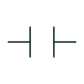
Normally open contact
A contact shown open in the normal state defined for its device.
Schematic
Explore electrical symbols, functional blocks and circuit arrangements for switchgear, switchrooms, substations, switchyards and microgrids. Detailed explanations, drawing notes, public sources and original SVG/DXF illustrations.
A contact shown open in the normal state defined for its device.
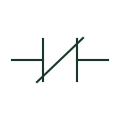
A contact shown closed in the normal state defined for its device.
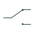
A contact arrangement switching a common connection between two contact paths.
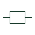
The operating element associated with a relay and its separately drawn contacts.
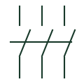
An electrically operated switching device commonly used for repeated switching duties.
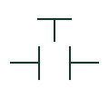
A pushbutton contact normally shown open before actuation.
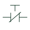
A pushbutton contact normally shown closed before actuation.
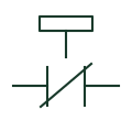
An identified emergency-stop operator and its documented contact arrangement.
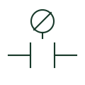
An operator switch selecting between documented control positions.

A visual indicator associated with a documented control or equipment condition.
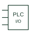
A controller interface point connecting field signals to an identified module channel.
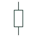
A resistive component with its value and purpose documented separately.
Understand symbols, equipment tags and function numbers—and know when a generic object needs a manufacturer drawing.
In plain English
Electrical symbols are shorthand for equipment, functions and connections. They let you follow how a circuit works without drawing every physical detail.
On a microgrid single-line diagram, a current-transformer symbol marks a measurement point and a breaker symbol marks where a circuit can be disconnected. Their labels identify the actual equipment.
Follow the connected lines to trace power or control signals. Use the project legend to interpret symbols and the selected manufacturer's drawings for dimensions and terminal connections.