Understand the difference.
Compare the meaning, drawing context and source references of two entries. A similar graphic or shared abbreviation does not establish equivalence.
JK-FF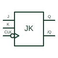
SymbolsNegative-edge JK flip-flop
Updates or toggles its stored state from J and K inputs at the selected negative clock edge.
- Drawing use
- Schematic
- Application
- Logic & signals
- Reference family
- Manufacturer
A distinction that matters
JK input combinations define hold, set, reset or toggle behaviour; the clock-edge indication must match the selected device.
D-FF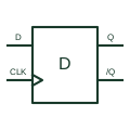
SymbolsPositive-edge D flip-flop
Captures its data input at the documented positive clock edge and retains that digital state.
- Drawing use
- Schematic
- Application
- Logic & signals
- Reference family
- Manufacturer
A distinction that matters
An edge-triggered flip-flop differs from a transparent latch; data timing relative to the clock remains essential.
Original educational previews. Follow the source references on each full entry for the appropriate standard or selected product.