PLC I/O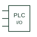
PLC input / output
A controller interface point connecting field signals to an identified module channel.
Schematic
Coordinates the steps of a machine or switching sequence.
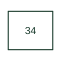
Coordinates the steps of a machine or switching sequence.
In a drafting package, connect this reference to the sequence step inputs and transition conditions. The associated drawing should trace the step outputs and unit sequence diagram; the number identifies the role and does not specify the terminal arrangement, ratings or operating settings.
A master sequence device sequences operations; device 10 determines the order of multiple units.
These public references support the explanation and provide further detail. Their graphics and downloadable files remain with their publishers.
Public manufacturer number/name association. Drafting explanations are independently written.
Normative device-number publication; exact edition wording and compliance require the licensed standard.
This illustration was authored independently by Elora Grid to explain the concept. It is not reproduced from a customer drawing, an official standard graphic or a manufacturer CAD file. Its correspondence to an exact IEC or IEEE symbol identifier has not been certified.
SVG and DXF downloads contain this original artwork. DXF uses unscaled drawing units; a GA envelope supplies no product dimensions, clearances or fabrication information. Original artwork is available under CC BY 4.0. Third-party references retain their own terms.
Elora Grid helps electrical teams work with drawings, specifications and equipment information. Explore the drafting workflow or join the early-access waitlist.