51
Time overcurrent
An overcurrent function with a documented time characteristic.
Protection functions
Supervises phase overcurrent using the selected time-current characteristic or intentional operating delay.
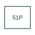
Supervises phase overcurrent using the selected time-current characteristic or intentional operating delay.
The drafting record should connect this function to the phase CT inputs and coordination-study reference, then trace the phase time-overcurrent output and protected breaker. Keep the complete designation and equipment tag together so that the SLD, relay logic and terminal schedule describe the same implementation.
The cited mapping is a public manufacturer example (Eaton ETR family). Suffixes are not universal equivalences across products, and this reference supplies neither a protection setting nor certification of the selected scheme.
51P identifies phase overcurrent timing; the symbol alone does not choose an IEC or IEEE curve family.
These public references support the explanation and provide further detail. Their graphics and downloadable files remain with their publishers.
Public primary-source function or application mapping used to identify this designation; wording and drafting notes are original.
Device-number and suffix convention. This page is not a reproduction of the full licensed standard.
This illustration was authored independently by Elora Grid to explain the concept. It is not reproduced from a customer drawing, an official standard graphic or a manufacturer CAD file. Its correspondence to an exact IEC or IEEE symbol identifier has not been certified.
SVG and DXF downloads contain this original artwork. DXF uses unscaled drawing units; a GA envelope supplies no product dimensions, clearances or fabrication information. Original artwork is available under CC BY 4.0. Third-party references retain their own terms.
Elora Grid helps electrical teams work with drawings, specifications and equipment information. Explore the drafting workflow or join the early-access waitlist.