32
Directional power
A function responding to power with a specified direction and operating condition.
Protection functions
Combines voltage and power directional criteria in the specified control or protection arrangement.
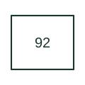
Combines voltage and power directional criteria in the specified control or protection arrangement.
In a drafting package, connect this reference to the voltage and current measurement references. The associated drawing should trace the permitted or blocked operating action; the number identifies the role and does not specify the terminal arrangement, ratings or operating settings.
This designation is useful when reading machine and legacy control drawings. Retain the documented function on an existing drawing and consult the original equipment manual before assigning it to a new design.
This specialist combined reference requires a scheme description; it should not replace separate modern function labels without justification.
These public references support the explanation and provide further detail. Their graphics and downloadable files remain with their publishers.
Public manufacturer number/name association. Drafting explanations are independently written.
Normative device-number publication; exact edition wording and compliance require the licensed standard.
This illustration was authored independently by Elora Grid to explain the concept. It is not reproduced from a customer drawing, an official standard graphic or a manufacturer CAD file. Its correspondence to an exact IEC or IEEE symbol identifier has not been certified.
SVG and DXF downloads contain this original artwork. DXF uses unscaled drawing units; a GA envelope supplies no product dimensions, clearances or fabrication information. Original artwork is available under CC BY 4.0. Third-party references retain their own terms.
Elora Grid helps electrical teams work with drawings, specifications and equipment information. Explore the drafting workflow or join the early-access waitlist.