ATS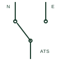
Automatic transfer switch
A mechanically switched changeover device that automatically moves a load from a failed normal source to an alternate source.
SLD / Schematic
An automatic transfer switch paired with a manual bypass switch so the ATS can be isolated for maintenance without losing the load.
In plain English
A bypass-isolation transfer switch combines an automatic transfer switch with a parallel manual bypass switch. The bypass can connect the load directly to either source while the automatic switch is withdrawn or isolated, so maintenance and testing can proceed without interrupting critical loads such as hospital or emergency circuits.
Single-line diagrams draw the automatic changeover in one path and a manually operated changeover in parallel, with isolating contacts on the automatic unit. Interlocks prevent the bypass from connecting the load to a source different from the one the automatic switch is using at the moment of bypass.
The symbol does not show the interlock sequence or whether the bypass operation is load-break. Operators need the switching procedure to use it safely.
An automatic transfer switch paired with a manual bypass switch so the ATS can be isolated for maintenance without losing the load. A bypass-isolation switch adds a manual path around the ATS; a plain ATS must be not supplied with operating power for maintenance.
Read the source: Transfer switch fundamentals · Generator switchgear and paralleling controls
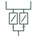
A bypass-isolation transfer switch combines an automatic transfer switch with a parallel manual bypass switch. The bypass can connect the load directly to either source while the automatic switch is withdrawn or isolated, so maintenance and testing can proceed without interrupting critical loads such as hospital or emergency circuits.
Single-line diagrams draw the automatic changeover in one path and a manually operated changeover in parallel, with isolating contacts on the automatic unit. Interlocks prevent the bypass from connecting the load to a source different from the one the automatic switch is using at the moment of bypass.
The symbol does not show the interlock sequence or whether the bypass operation is load-break. Operators need the switching procedure to use it safely.
A bypass-isolation switch adds a manual path around the ATS; a plain ATS must be de-energised for maintenance.
These public references support the explanation and provide further detail. Their graphics and downloadable files remain with their publishers.
Public transfer switch fundamentals.
Public generator switchgear context.
This illustration was authored independently by Elora Grid to explain the concept. It is not reproduced from a customer drawing, an official standard graphic or a manufacturer CAD file. Its correspondence to an exact IEC or IEEE symbol identifier has not been certified.
SVG and DXF downloads contain this original artwork. DXF uses unscaled drawing units; a GA envelope supplies no product dimensions, clearances or fabrication information. Original artwork is available under CC BY 4.0. Third-party references retain their own terms.
A mechanically switched changeover device that automatically moves a load from a failed normal source to an alternate source.
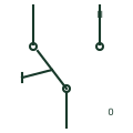
An operator-moved changeover switch that selects which of two sources supplies a load, with an off position between them.

An equipment assembly connecting a load to the selected supply source.
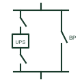
An arrangement of interlocked switches that routes the load around a UPS so the UPS can be isolated for work.
Elora Grid helps electrical teams work with drawings, specifications and equipment information. Explore the drafting workflow or join the early-access waitlist.