LEVEL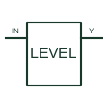
Logic voltage-level translator
Transfers digital information between the documented logic-voltage domains.
Schematic
In plain English
An I2C level translator adapts the specified logic-voltage levels between compatible bus sections.
Two devices with different supported logic supplies may communicate through a suitable translator.
Label the supply voltage domain on each side and show both I2C signals. Voltage translation lets compatible logic interfaces work across selected voltage levels; it does not automatically create a safety-rated isolation barrier. Follow the chosen translator’s requirements for pull-ups and power sequencing.
No. Changing logic-voltage levels is distinct from transferring information across an electrical isolation barrier. Use an explicitly specified isolating interface if that separation is required.
Read the source: I2C, I3C and SPI interface functions
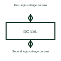
Voltage translation is different from electrical isolation across a rated barrier.
These public references support the explanation and provide further detail. Their graphics and downloadable files remain with their publishers.
I2C, I3C and SPI interface functions: public technical context for the named function. Product and compliance details remain with the publisher.
This illustration was authored independently by Elora Grid to explain the concept. It is not reproduced from a customer drawing, an official standard graphic or a manufacturer CAD file. Its correspondence to an exact IEC or IEEE symbol identifier has not been certified.
SVG and DXF downloads contain this original artwork. DXF uses unscaled drawing units; a GA envelope supplies no product dimensions, clearances or fabrication information. Original artwork is available under CC BY 4.0. Third-party references retain their own terms.
Transfers digital information between the documented logic-voltage domains.
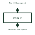
An I2C bus buffer separates or supports selected parts of an I2C connection.
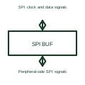
An SPI buffer supports the selected digital signal paths between an SPI controller and its peripheral interface.
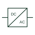
An identified interface converting electrical power between documented circuit forms.
Elora Grid helps electrical teams work with drawings, specifications and equipment information. Explore the drafting workflow or join the early-access waitlist.