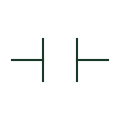
Coil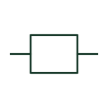
Relay coil
The operating element associated with a relay and its separately drawn contacts.
Schematic
This indication identifies the disconnected state of a mechanical coupling.
Autodesk IEC-60617 Symbol Preview — Mechanical coupling qualifiers; vendor family reference, not certified IEC geometry or database identifier.
Shown as an independently authored educational illustration. Use the cited publication and drawing legend to verify the required drafting form.
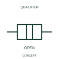
This indication identifies the disconnected state of a mechanical coupling. The driving and driven elements are represented without an engaged torque or motion-transmission relationship in this state. Either element can still have electrical connections.
Use the state diagram or mechanism schedule to define what causes engagement. The disconnected coupling mark should not be substituted for a power isolation symbol.
A disconnected coupling state is separate from the isolation of an electrical supply.
These public references support the explanation and provide further detail. Their graphics and downloadable files remain with their publishers.
Official public publisher family name and reference context; vendor identifiers and graphics are distinct from licensed IEC database content.
This illustration was authored independently by Elora Grid to explain the concept. It is not reproduced from a customer drawing, an official standard graphic or a manufacturer CAD file. Its correspondence to an exact IEC or IEEE symbol identifier has not been certified.
SVG and DXF downloads contain this original artwork. DXF uses unscaled drawing units; a GA envelope supplies no product dimensions, clearances or fabrication information. Original artwork is available under CC BY 4.0. Third-party references retain their own terms.
Elora Grid helps electrical teams work with drawings, specifications and equipment information. Explore the drafting workflow or join the early-access waitlist.