OR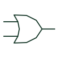
OR gate
A positive-logic element whose output is true when at least one input is true.
Schematic
IEC rectangular OR element labelled ≥1, meaning at least one active input is needed to activate the output.
In plain English
The ≥1 additional drawing mark inside a rectangular outline identifies an OR function. The notation literally reads as at least one input active, which is why the same family of symbols uses ≥m for threshold functions in other contexts. Inputs are drawn on the left and the output on the right unless an arrow indicates otherwise.
On trip logic and permissive diagrams the ≥1 box often collects several fault signals into a single trip command. Because every input is equal, the drawing should label each incoming signal with its source tag so that a reader can trace which condition caused the output during testing.
The symbol does not state whether the inputs are latched, filtered or time-delayed. Any such behaviour must be shown by separate elements or by labels; the OR box itself is purely combinative.
IEC rectangular OR element labelled ≥1, meaning at least one active input is needed to activate the output. A box marked 1 alone is a buffer or single-input element; ≥1 is required for the OR function.
Read the source: Overview of IEEE Standard 91-1984: explanation of logic symbols (SDYZ001A) · SN74HC32 — OR gate logic
Qualifying-symbol and dependency conventions as explained in TI's public overview of IEEE Std 91-1984, which incorporates IEC 617-12 work. Independent educational drawing; not certified IEC geometry or an IEC database identifier. The counterpart is the matching functional concept; no equivalence of every detailed standard graphic is asserted.
Shown as an independently authored educational illustration. Use the cited publication and drawing legend to verify the required drafting form.
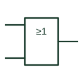
The ≥1 qualifier inside a rectangular outline identifies an OR function. The notation literally reads as at least one input active, which is why the same family of symbols uses ≥m for threshold functions in other contexts. Inputs are drawn on the left and the output on the right unless an arrow indicates otherwise.
On trip logic and permissive diagrams the ≥1 box often collects several fault signals into a single trip command. Because every input is equal, the drawing should label each incoming signal with its source tag so that a reader can trace which condition caused the output during testing.
The symbol does not state whether the inputs are latched, filtered or time-delayed. Any such behaviour must be shown by separate elements or by labels; the OR box itself is purely combinative.
A box marked 1 alone is a buffer or single-input element; ≥1 is required for the OR function.
These public references support the explanation and provide further detail. Their graphics and downloadable files remain with their publishers.
Defines ≥1 as the OR qualifier and explains why it was chosen.
Manufacturer OR gate documentation.
This illustration was authored independently by Elora Grid to explain the concept. It is not reproduced from a customer drawing, an official standard graphic or a manufacturer CAD file. Its correspondence to an exact IEC or IEEE symbol identifier has not been certified.
SVG and DXF downloads contain this original artwork. DXF uses unscaled drawing units; a GA envelope supplies no product dimensions, clearances or fabrication information. Original artwork is available under CC BY 4.0. Third-party references retain their own terms.
A positive-logic element whose output is true when at least one input is true.
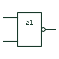
IEC ≥1 element with a negated output; the output is active only when none of the inputs are active.
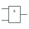
Rectangular IEC-style AND element marked with an ampersand; the output is active only when every input is active.
Elora Grid helps electrical teams work with drawings, specifications and equipment information. Explore the drafting workflow or join the early-access waitlist.