S R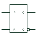
IEC SR latch (rectangular form)
Rectangular IEC bistable with S and R inputs that set or reset the stored state immediately.
IEC
Dependency labels Sm and Rm: the affected output behaves as if set or reset when the affecting input is active.
In plain English
S and R dependencies specify the internal state of an output when both set and reset conditions could be active together. An Rm input at its internal 1 state makes the affected output react as it would to S=0, R=1; an Sm input does the opposite. At 0 they have no effect.
These labels are used where a storage element must have a defined priority between set and reset. A reader can see from the symbol whether set or reset dominates, which matters in latching alarm and interlock logic.
Plain S and R labels without numbers are the ordinary set and reset inputs of a bistable element. The dependency form only applies when a number follows the letter.
Dependency labels Sm and Rm: the affected output behaves as if set or reset when the affecting input is active. An ordinary R input resets the element directly; Rm dependency states the reaction of particular outputs.
Read the source: Overview of IEEE Standard 91-1984: explanation of logic symbols (SDYZ001A)
Qualifying-symbol and dependency conventions as explained in TI's public overview of IEEE Std 91-1984, which incorporates IEC 617-12 work. Independent educational drawing; not certified IEC geometry or an IEC database identifier.
Shown as an independently authored educational illustration. Use the cited publication and drawing legend to verify the required drafting form.
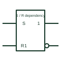
S and R dependencies specify the internal state of an output when both set and reset conditions could be active together. An Rm input at its internal 1 state makes the affected output react as it would to S=0, R=1; an Sm input does the opposite. At 0 they have no effect.
These labels are used where a storage element must have a defined priority between set and reset. A reader can see from the symbol whether set or reset dominates, which matters in latching alarm and interlock logic.
Plain S and R labels without numbers are the ordinary set and reset inputs of a bistable element. The dependency form only applies when a number follows the letter.
An ordinary R input resets the element directly; Rm dependency states the reaction of particular outputs.
These public references support the explanation and provide further detail. Their graphics and downloadable files remain with their publishers.
S (set) and R (reset) dependencies and the summary table.
This illustration was authored independently by Elora Grid to explain the concept. It is not reproduced from a customer drawing, an official standard graphic or a manufacturer CAD file. Its correspondence to an exact IEC or IEEE symbol identifier has not been certified.
SVG and DXF downloads contain this original artwork. DXF uses unscaled drawing units; a GA envelope supplies no product dimensions, clearances or fabrication information. Original artwork is available under CC BY 4.0. Third-party references retain their own terms.
Rectangular IEC bistable with S and R inputs that set or reset the stored state immediately.
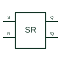
Retains a digital state that is changed by the defined set or reset input conditions.
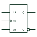
IEC bistable with 1S and 1R inputs that act only under C1 control, giving a synchronous set-reset function.
Elora Grid helps electrical teams work with drawings, specifications and equipment information. Explore the drafting workflow or join the early-access waitlist.