MGC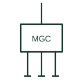
Microgrid controller
The supervisory controller that dispatches sources, storage and loads and manages islanding and reconnection of a microgrid.
SLD / Schematic
The plant-level controller that measures at the connection point and sets inverter or turbine outputs to meet grid requirements.
In plain English
A power plant controller measures voltage, current, active and reactive power at the plant connection point and adjusts setpoints of all inverters or turbines to meet the network operator's requirements. Typical functions include active power limits, ramp rates, frequency response, voltage or reactive power control and power factor control.
Drawings show a control block with measurement inputs from the connection point CTs and VTs, a communication network to each inverter or turbine, and a link to the network operator's control system. A meter at the point of connection is usually the measurement source.
The controller's response speed is slower than the inverter internal controls, so fast events are still handled by the devices themselves. The symbol does not show control modes, settings or the response time agreed with the network operator.
The plant-level controller that measures at the connection point and sets inverter or turbine outputs to meet grid requirements. A power plant controller manages one generating plant at its connection point; a microgrid controller also manages loads and islanding.
Read the source: Solar electrical system architecture · Reliable hybrid power and microgrid solutions
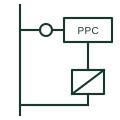
A power plant controller measures voltage, current, active and reactive power at the plant connection point and adjusts setpoints of all inverters or turbines to meet the network operator's requirements. Typical functions include active power limits, ramp rates, frequency response, voltage or reactive power control and power factor control.
Drawings show a control block with measurement inputs from the connection point CTs and VTs, a communication network to each inverter or turbine, and a link to the network operator's control system. A meter at the point of connection is usually the measurement source.
The controller's response speed is slower than the inverter internal controls, so fast events are still handled by the devices themselves. The symbol does not show control modes, settings or the response time agreed with the network operator.
A power plant controller manages one generating plant at its connection point; a microgrid controller also manages loads and islanding.
These public references support the explanation and provide further detail. Their graphics and downloadable files remain with their publishers.
Public solar plant architecture context.
Public hybrid plant control context.
This illustration was authored independently by Elora Grid to explain the concept. It is not reproduced from a customer drawing, an official standard graphic or a manufacturer CAD file. Its correspondence to an exact IEC or IEEE symbol identifier has not been certified.
SVG and DXF downloads contain this original artwork. DXF uses unscaled drawing units; a GA envelope supplies no product dimensions, clearances or fabrication information. Original artwork is available under CC BY 4.0. Third-party references retain their own terms.
The supervisory controller that dispatches sources, storage and loads and manages islanding and reconnection of a microgrid.
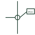
A marker on a single-line diagram identifying where a customer installation or microgrid meets the public network.
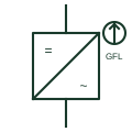
An inverter that tracks an existing network voltage with a phase-locked loop and injects controlled current into it.
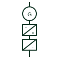
A wind turbine whose entire generator output passes through a full-rated back-to-back converter before reaching the network.
Elora Grid helps electrical teams work with drawings, specifications and equipment information. Explore the drafting workflow or join the early-access waitlist.