Coil
Relay coil
The operating element associated with a relay and its separately drawn contacts.
Schematic
An independently authored application reference. The drawing shows the named function or circuit relationship; use the project legend and selected equipment documentation for its drafting form and connections.
Browse this installation focusIn plain English
Identifies the supply dedicated to the assigned protective relays and their electronics.
In a switchgear lineup, separate protected branches may feed trip coils, closing coils and protection electronics. Their alarm contacts help the station controller identify which operating capability is unavailable. For this reference, the drawing identifies “Protected auxiliary supply” at the input and “Protection-device power” at the output. Relay power is distinct from trip-coil power.
Start at the named input: Protected auxiliary supply. Identify its source device or document and the state represented on the drawing. Follow the named output: Protection-device power. Cross-reference its destination and separate the command from confirmation that the equipment responded.
Read the source: SEL-RPM redundant power module
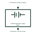
Identifies the supply dedicated to the assigned protective relays and their electronics. Control power supplies the command, protection and indication equipment associated with a switchgear assembly. The drawing must distinguish the source, each distribution branch and the functions lost if that branch fails.
In a switchgear lineup, separate protected branches may feed trip coils, closing coils and protection electronics. Their alarm contacts help the station controller identify which operating capability is unavailable. For this reference, the drawing identifies “Protected auxiliary supply” at the input and “Protection-device power” at the output. Relay power is distinct from trip-coil power.
Follow the actual positive, negative or neutral returns and the protective device on each branch. A healthy voltage indication does not establish that every downstream path can deliver its required operating current. The functional block is an independent explanation of this named application. Equipment-specific ratings, terminal connections and operating conditions must be established in the project documentation.
Relay power is distinct from trip-coil power. This reference describes the named application; it does not establish a new IEC graphical symbol, an ANSI device-function number or an exact manufacturer connection diagram.
These public references support the explanation and provide further detail. Their graphics and downloadable files remain with their publishers.
Public technical context for switchgear control-power supervision. Independent AC and DC sources for station auxiliary power. The application text and educational graphic are independently authored; the publisher does not certify this representation.
This illustration was authored independently by Elora Grid to explain the concept. It is not reproduced from a customer drawing, an official standard graphic or a manufacturer CAD file. Its correspondence to an exact IEC or IEEE symbol identifier has not been certified.
SVG and DXF downloads contain this original artwork. Original artwork is available under CC BY 4.0. Third-party references retain their own terms.
The operating element associated with a relay and its separately drawn contacts.
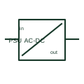
An AC/DC power supply converts a documented AC input to a DC output for control or auxiliary circuits.
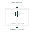
Shows the separately identified power path serving local operating indications.
Elora Grid helps electrical teams work with drawings, specifications and equipment information. Explore the drafting workflow or join the early-access waitlist.