SHVD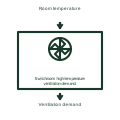
Switchroom high-temperature ventilation demand
Generates a ventilation request from the monitored room-temperature condition.
Functional block
Explore electrical symbols, functional blocks and circuit arrangements for switchgear, switchrooms, substations, switchyards and microgrids. Detailed explanations, drawing notes, public sources and original SVG/DXF illustrations.
Generates a ventilation request from the monitored room-temperature condition.
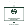
Restrains the specified ventilation action when the room reaches its defined low-temperature condition.
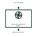
Assigns the available room ventilation fans to the documented duty and standby roles.
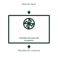
Transfers the documented ventilation duty when the active fan becomes unavailable.
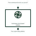
Checks the feedback that confirms a commanded fan is operating.
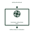
Reports missing or inadequate airflow under the documented supervised ventilation condition.
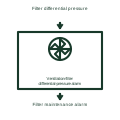
Reports the defined pressure-difference condition across the monitored ventilation filter.
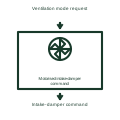
Requests the intake-damper position needed by the selected room operating mode.
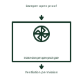
Uses the intake-damper feedback as a condition of the assigned ventilation operation.
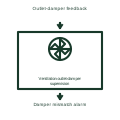
Monitors the documented exhaust-damper position against the ventilation request.
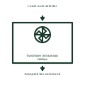
Selects the permitted local or automatic command path for the room fan.
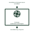
Initiates the documented heater or conditioning action for condensation management.
Understand symbols, equipment tags and function numbers—and know when a generic object needs a manufacturer drawing.
In plain English
Electrical symbols are shorthand for equipment, functions and connections. They let you follow how a circuit works without drawing every physical detail.
On a microgrid single-line diagram, a current-transformer symbol marks a measurement point and a breaker symbol marks where a circuit can be disconnected. Their labels identify the actual equipment.
Follow the connected lines to trace power or control signals. Use the project legend to interpret symbols and the selected manufacturer's drawings for dimensions and terminal connections.