SSBA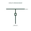
Single-bus single-breaker bay arrangement
Connects the assigned circuit through its breaker to one common bus.
Circuit arrangement
Explore electrical symbols, functional blocks and circuit arrangements for switchgear, switchrooms, substations, switchyards and microgrids. Detailed explanations, drawing notes, public sources and original SVG/DXF illustrations.
Connects the assigned circuit through its breaker to one common bus.
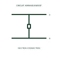
Divides a common bus into identified sections with a defined section connection.
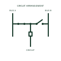
Provides the assigned bay with selected connection paths to two buses through one circuit breaker.
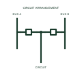
Provides separately switched breaker paths between the assigned circuit and two buses.
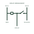
Provides the documented transfer-bus path used alongside the main bus connection.
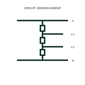
Connects two circuits through the documented three-breaker diameter between buses.
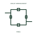
Connects circuit takeoffs between adjacent switching devices in the documented bus ring.
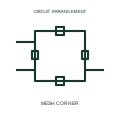
Shows the assigned circuit connections around a documented mesh corner.
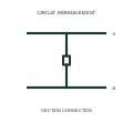
Connects the assigned bus sections through their defined coupler breaker path.
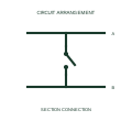
Identifies the isolating connection separating the assigned bus conductor sections.
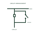
Shows the alternate path bypassing the assigned bay breaker under its documented configuration.
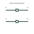
Identifies the documented coupler connections between corresponding sections of two buses.
Understand symbols, equipment tags and function numbers—and know when a generic object needs a manufacturer drawing.
In plain English
Electrical symbols are shorthand for equipment, functions and connections. They let you follow how a circuit works without drawing every physical detail.
On a microgrid single-line diagram, a current-transformer symbol marks a measurement point and a breaker symbol marks where a circuit can be disconnected. Their labels identify the actual equipment.
Follow the connected lines to trace power or control signals. Use the project legend to interpret symbols and the selected manufacturer's drawings for dimensions and terminal connections.