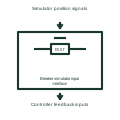
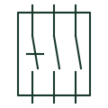
Understand the difference. Compare the meaning, drawing context and source references of two entries. A similar graphic or shared abbreviation does not establish equivalence.
First referenceCurrent transformer · CT Voltage transformer · VT / PT Circuit breaker · CB Disconnector · Isolator Load-break switch · LBS Earthing switch · ES Fuse · FU Busbar · Bus Normally open contact · NO Normally closed contact · NC Changeover contact · CO Relay coil · Coil Contactor · KM Normally open pushbutton · PB NO Normally closed pushbutton · PB NC Emergency-stop operator · E-stop Selector switch · SS Indicator lamp · Lamp Terminal connection · Terminal CT test terminal · CT test Power transformer · TX Generator · GEN Three-phase motor · M PLC input / output · PLC I/O Capacitor · C Resistor · R Protective earth · PE Battery · BAT Power converter / inverter · PCS Single-pole circuit breaker · CB 1P Thermal circuit breaker · CB TH Thermal-magnetic circuit breaker · CB TM Current-limiting circuit breaker · CB LIM Residual-current circuit breaker · RCCB Residual-current breaker with overcurrent protection · RCBO Circuit breaker with undervoltage release · CB UV Circuit breaker with electronic trip unit · CB ETU Miniature circuit breaker · MCB Moulded-case circuit breaker · MCCB Air circuit breaker · ACB Additional circuit-breaker pole · CB POLE Switch-disconnector · SD Lockable disconnector · DS LOCK Lockable switch-disconnector · SD LOCK Three-position disconnector · DS 3POS Semiconductor power switch · SSW Unidirectional semiconductor power switch · SSW UNI Two-pole power switch · SW 2P Disconnector auxiliary NO contact · DS AUX NO Disconnector auxiliary NC contact · DS AUX NC Fused switch · SW FUSE Fuse-switch · FUSE SW Additional fused-switch pole · FUSE POLE General-purpose full-range fuse · gG Motor short-circuit fuse · aM Motor full-range fuse · gM Current transformer with two secondaries · CT 2SEC Tapped-secondary current transformer · CT TAP Current transformer with primary conductor indication · CT PRI Core-balance current transformer · CBCT Residual connection of phase CTs · CT RES Single-phase two-winding transformer · TX 1PH Electrostatically screened transformer · TX SCREEN Three-winding transformer · TX 3W Adjustable-ratio transformer · TX ADJ Single-phase autotransformer · AT 1PH Three-phase star autotransformer · AT 3PH Y Star-delta transformer · TX Y-D Delta-star transformer · TX D-Y Delta-delta transformer · TX D-D Star-star transformer · TX Y-Y Star-zigzag transformer · TX Y-Z Star-star-delta three-winding transformer · TX Y-Y-D Delta winding connection · DELTA Open-delta winding connection · OPEN D Star winding connection · STAR Y Star winding with accessible neutral · Y N Zigzag winding connection · ZIGZAG Mechanically latched relay coil · K LATCH Relay reset coil · K RESET Solid-state relay · SSR Polarised relay coil · K POL AC relay coil · K AC High-speed relay · K FAST Measuring relay · K MEAS Relay coil with diode suppression · K DIODE Relay coil with diode and LED · K D LED Relay coil with capacitor suppression · K CAP Relay coil with RC suppression · K RC Counter relay with manual reset · COUNT MAN Counter relay with electrical reset · COUNT ELEC Non-resettable counter relay · COUNT TOTAL On-delay timer relay · TON Off-delay timer relay · TOFF On-delay normally-open contact · TON NO On-delay normally-closed contact · TON NC Off-delay normally-open contact · TOFF NO Off-delay normally-closed contact · TOFF NC Maintained normally-open contact · NO HOLD Maintained normally-closed contact · NC HOLD Manually unlatched NO contact · NO UNLATCH Manually unlatched NC contact · NC UNLATCH Early-make normally-open contact · NO EARLY Late-make normally-open contact · NO LATE Early-break normally-closed contact · NC EARLY Late-break normally-closed contact · NC LATE Make-before-break changeover contact · MBB Motor overload trip NC contact · OL NC Motor overload alarm NO contact · OL NO Illuminated normally-open pushbutton · PB NO LAMP Illuminated normally-closed pushbutton · PB NC LAMP Maintained normally-open pushbutton · PB NO HOLD Maintained normally-closed pushbutton · PB NC HOLD Key-operated normally-open switch · KEY NO Key-operated normally-closed switch · KEY NC Latched key-operated switch · KEY HOLD Pull-cord switch · PULL CORD Foot-operated switch · FOOT Lever-operated switch · LEVER Three-position maintained selector · SEL 3 HOLD Three-position selector returning from left · SEL 3 LRET Three-position selector returning from right · SEL 3 RRET Three-position centre-return selector · SEL 3 CRET Three-position key selector · KEY SEL 3 Four-position maintained selector · SEL 4 HOLD Four-position key selector · KEY SEL 4 Normally-open limit switch · LS NO Normally-closed limit switch · LS NC Roller-operated limit switch · LS ROLLER Cam-operated limit switch · LS CAM Pressure switch NO · PS NO Pressure switch NC · PS NC Temperature switch NO · TS NO Temperature switch NC · TS NC Self-operating thermal switch · TS SELF Float level switch NO · LS FLOAT NO Float level switch NC · LS FLOAT NC Liquid flow switch · FS LIQ Gas flow switch · FS GAS Inductive proximity switch · PROX IND Three-wire inductive proximity switch · PROX IND 3W Capacitive proximity switch · PROX CAP Magnetic proximity switch · PROX MAG Photoelectric emitter-receiver switch · PHOTO Thermocouple · TC Resistance temperature detector · RTD Voltmeter · V Ammeter · A Power-factor meter · PF Phase-angle meter · PHASE Frequency meter · Hz Temperature indicator · TEMP Tachometer · RPM Running-hours meter · HOURS Ampere-hour meter · Ah Recording wattmeter · W REC Reactive-power meter · var Synchronoscope · SYNC SCOPE Active-power indicator · kW Differential voltmeter · DELTA V Active-energy meter · kWh Reactive-energy meter · kvarh Maximum-current monitoring relay · I HIGH Minimum-current monitoring relay · I LOW Current window monitoring relay · I WINDOW Differential-current measuring relay · I DIFF Residual-voltage monitoring relay · U RES Loss-of-voltage monitoring relay · U LOSS Phase-loss monitoring relay · PH LOSS Frequency monitoring relay · f MON Minimum active-power relay · P LOW Feed-through terminal block · TB FEED Disconnect terminal block · TB DISC Knife-disconnect terminal · TB KNIFE Fuse terminal block · TB FUSE Diode terminal block · TB DIODE Component terminal block · TB COMP Multilevel terminal block · TB LEVEL Multi-conductor terminal block · TB MULTI Protective-earth terminal block · TB PE Sensor terminal block · TB SENSOR Actuator terminal block · TB ACT Plug-in terminal block · TB PLUG High-current terminal block · TB POWER Terminal jumper bridge · TB BRIDGE Plug and socket connector pair · PLUG SOCKET Connector plug half · PLUG Connector socket half · SOCKET Wire splice · SPLICE Earth connection · EARTH Functional earth · FE Protective equipotential bonding · BOND PE Functional equipotential bonding · BOND FE Surge arrester · SA Gas-discharge protection tube · GDT Spark-gap protective element · SPARK GAP Variable resistor · R VAR Potentiometer · POT Light-dependent resistor · LDR Heating element · HEATER RC network · RC Varistor · VDR Current-measuring shunt · SHUNT Electrolytic capacitor · C ELEC Feedthrough capacitor · C FEED Adjustable capacitor · C ADJ Three-phase power-factor capacitor · CAP 3PH Reactor · L Iron-core reactor · L IRON Gapped-core inductor · L GAP Adjustable-core inductor · L ADJ Diode · D Photodiode · PD Zener diode · ZD DIAC · DIAC Single-phase bridge rectifier · BR 1PH Three-phase bridge rectifier · BR 3PH Silicon-controlled rectifier · SCR Gate-turn-off thyristor · GTO TRIAC · TRIAC Bidirectional breakdown diode · TVS BI Single-phase AC motor · M 1PH AC Single-phase motor with fan · M 1PH FAN Three-phase AC motor · M 3PH Three-phase motor with fan · M 3PH FAN Wound-rotor induction motor · M WR Three-phase synchronous motor · M 3PH SYNC DC motor · M DC Permanent-magnet DC motor · M DC PM Series-excited DC motor · M DC SERIES Separately excited DC motor · M DC SEP DC generator · G DC Compound-excited DC generator · G DC COMP Three-phase synchronous generator · G 3PH SYNC Permanent-magnet synchronous generator · G 3PH PM AC-to-DC power supply · PSU AC-DC DC-to-DC converter · DC-DC DC-to-AC inverter · INV DC-AC DC uninterruptible power supply · UPS DC AC uninterruptible power supply · UPS AC Capacitor buffer module · BUFFER CAP Redundant power-supply decoupling module · PSU RED Analog current signal isolator · ISO I-I Temperature measuring transducer · TEMP TX Photovoltaic inverter · PV INV Single-phase AC source · AC 1PH Three-phase AC source · AC 3PH Photovoltaic generator · PV GEN Solar generating station · SOLAR STN Wind generating station · WIND STN Substation · SUBSTATION Converter substation · CONV STN Generic electrical load · LOAD Transformer-fed indicator lamp · LAMP TX Push-to-test indicator lamp · LAMP TEST LED indicator lamp · LAMP LED Flashing indicator lamp · LAMP FLASH Flashing beacon · BEACON FLASH Rotating beacon · BEACON ROT PLC digital input · DI PLC relay output · DO RELAY PLC transistor output · DO TRANS PLC analog input · AI PLC analog output · AO PLC temperature input · TI Capacitor voltage transformer · CVT / CCVT ANSI/IEEE circuit breaker symbol · CB ANSI/IEEE thermal circuit breaker symbol · CB TH ANSI/IEEE thermal-magnetic circuit breaker symbol · CB TM ANSI/IEEE current-limiting circuit breaker symbol · CB LIM ANSI/IEEE circuit breaker with undervoltage release symbol · CB UV ANSI/IEEE circuit breaker with electronic trip unit symbol · CB ETU ANSI/IEEE disconnector symbol · Isolator ANSI/IEEE switch-disconnector symbol · SD ANSI/IEEE lockable disconnector symbol · DS LOCK ANSI/IEEE lockable switch-disconnector symbol · SD LOCK ANSI/IEEE fused switch symbol · SW FUSE ANSI/IEEE fuse symbol · FU ANSI/IEEE fuse-switch symbol · FUSE SW ANSI/IEEE current transformer symbol · CT ANSI/IEEE current transformer with two secondaries symbol · CT 2SEC ANSI/IEEE tapped-secondary current transformer symbol · CT TAP ANSI/IEEE voltage transformer symbol · VT / PT ANSI/IEEE power transformer symbol · TX ANSI/IEEE electrostatically screened transformer symbol · TX SCREEN ANSI/IEEE three-winding transformer symbol · TX 3W ANSI/IEEE adjustable-ratio transformer symbol · TX ADJ ANSI/IEEE single-phase autotransformer symbol · AT 1PH ANSI/IEEE reactor symbol · L ANSI/IEEE iron-core reactor symbol · L IRON ANSI/IEEE gapped-core inductor symbol · L GAP ANSI/IEEE adjustable-core inductor symbol · L ADJ ANSI/IEEE normally open contact symbol · NO ANSI/IEEE normally closed contact symbol · NC ANSI/IEEE changeover contact symbol · CO ANSI/IEEE relay coil symbol · Coil ANSI/IEEE mechanically latched relay coil symbol · K LATCH ANSI/IEEE relay reset coil symbol · K RESET ANSI/IEEE polarised relay coil symbol · K POL ANSI/IEEE ac relay coil symbol · K AC ANSI/IEEE relay coil with diode suppression symbol · K DIODE ANSI/IEEE relay coil with rc suppression symbol · K RC ANSI/IEEE on-delay timer relay symbol · TON ANSI/IEEE off-delay timer relay symbol · TOFF ANSI/IEEE maintained normally-open contact symbol · NO HOLD ANSI/IEEE maintained normally-closed contact symbol · NC HOLD ANSI/IEEE early-make normally-open contact symbol · NO EARLY ANSI/IEEE late-make normally-open contact symbol · NO LATE ANSI/IEEE early-break normally-closed contact symbol · NC EARLY ANSI/IEEE late-break normally-closed contact symbol · NC LATE ANSI/IEEE motor overload trip nc contact symbol · OL NC ANSI/IEEE motor overload alarm no contact symbol · OL NO ANSI/IEEE normally open pushbutton symbol · PB NO ANSI/IEEE normally closed pushbutton symbol · PB NC ANSI/IEEE illuminated normally-open pushbutton symbol · PB NO LAMP ANSI/IEEE illuminated normally-closed pushbutton symbol · PB NC LAMP ANSI/IEEE maintained normally-open pushbutton symbol · PB NO HOLD ANSI/IEEE maintained normally-closed pushbutton symbol · PB NC HOLD ANSI/IEEE selector switch symbol · SS ANSI/IEEE three-position maintained selector symbol · SEL 3 HOLD ANSI/IEEE three-position centre-return selector symbol · SEL 3 CRET ANSI/IEEE three-position key selector symbol · KEY SEL 3 ANSI/IEEE four-position maintained selector symbol · SEL 4 HOLD ANSI/IEEE four-position key selector symbol · KEY SEL 4 ANSI/IEEE normally-open limit switch symbol · LS NO ANSI/IEEE normally-closed limit switch symbol · LS NC ANSI/IEEE roller-operated limit switch symbol · LS ROLLER ANSI/IEEE pressure switch no symbol · PS NO ANSI/IEEE pressure switch nc symbol · PS NC ANSI/IEEE temperature switch no symbol · TS NO ANSI/IEEE temperature switch nc symbol · TS NC ANSI/IEEE float level switch no symbol · LS FLOAT NO ANSI/IEEE float level switch nc symbol · LS FLOAT NC ANSI/IEEE liquid flow switch symbol · FS LIQ ANSI/IEEE terminal connection symbol · Terminal ANSI/IEEE numbered terminal symbol · TERM 1 ANSI/IEEE plug and socket connector pair symbol · PLUG SOCKET ANSI/IEEE connector plug half symbol · PLUG ANSI/IEEE connector socket half symbol · SOCKET ANSI/IEEE wire splice symbol · SPLICE ANSI/IEEE protective earth symbol · PE ANSI/IEEE functional earth symbol · FE ANSI/IEEE resistor symbol · R ANSI/IEEE variable resistor symbol · R VAR ANSI/IEEE potentiometer symbol · POT ANSI/IEEE light-dependent resistor symbol · LDR ANSI/IEEE heating element symbol · HEATER ANSI/IEEE varistor symbol · VDR ANSI/IEEE current-measuring shunt symbol · SHUNT ANSI/IEEE capacitor symbol · C ANSI/IEEE electrolytic capacitor symbol · C ELEC ANSI/IEEE feedthrough capacitor symbol · C FEED ANSI/IEEE adjustable capacitor symbol · C ADJ ANSI/IEEE diode symbol · D ANSI/IEEE photodiode symbol · PD ANSI/IEEE zener diode symbol · ZD ANSI/IEEE single-phase bridge rectifier symbol · BR 1PH ANSI/IEEE silicon-controlled rectifier symbol · SCR ANSI/IEEE triac symbol · TRIAC ANSI/IEEE voltmeter symbol · V ANSI/IEEE ammeter symbol · A ANSI/IEEE power-factor meter symbol · PF ANSI/IEEE frequency meter symbol · Hz ANSI/IEEE recording wattmeter symbol · W REC ANSI/IEEE reactive-power meter symbol · var ANSI/IEEE synchronoscope symbol · SYNC SCOPE ANSI/IEEE running-hours meter symbol · HOURS ANSI/IEEE single-phase ac motor symbol · M 1PH AC ANSI/IEEE three-phase ac motor symbol · M 3PH ANSI/IEEE wound-rotor induction motor symbol · M WR ANSI/IEEE dc motor symbol · M DC ANSI/IEEE permanent-magnet dc motor symbol · M DC PM ANSI/IEEE three-phase synchronous generator symbol · G 3PH SYNC ANSI/IEEE dc generator symbol · G DC ANSI/IEEE indicator lamp symbol · Lamp ANSI/IEEE transformer-fed indicator lamp symbol · LAMP TX ANSI/IEEE push-to-test indicator lamp symbol · LAMP TEST ANSI/IEEE led indicator lamp symbol · LAMP LED ANSI/IEEE on-delay normally-open contact symbol · TON NO ANSI/IEEE on-delay normally-closed contact symbol · TON NC ANSI/IEEE off-delay normally-open contact symbol · TOFF NO ANSI/IEEE off-delay normally-closed contact symbol · TOFF NC Positive-operation direction qualifier · Q070109 Manual-operation qualifier · Q021301 Protected-access manual-operation qualifier · Q021302 Pushbutton-operation qualifier · Q021305 Emergency-operation qualifier · Q021308 Rotary-operation qualifier · Q021304 Key-operation qualifier · Q021313 Foot-operation qualifier · Q021310 Lever-operation qualifier · Q021311 Crank-operation qualifier · Q021214 Handwheel-operation qualifier · Q021309 Liquid-level actuation qualifier · Q021401 Event-count actuation qualifier · Q021402 Liquid-flow actuation qualifier · Q021403 Gas-flow actuation qualifier · Q021404 Motor-operation qualifier · Q021326 Timed-operation qualifier · Q021327 Roller-operation qualifier · Q021315 Cam-operation qualifier · Q021316 Cam-profile indication · Q021317 Switch-position function qualifier · Q070106 Isolation-function qualifier · Q070103 Switch-disconnector function qualifier · Q070104 Circuit-breaker function qualifier · Q070102 Power-contactor function qualifier · Q070101 Automatic-trip qualifier · Q070105 Spring-return qualifier · Q070107 Maintained-position qualifier · Q070108 One-way linear-motion qualifier · Q020401R Two-way linear-motion qualifier · Q020402 Transition indication · Q101101 One-way rotary-motion qualifier · Q020403 Two-way rotary-motion qualifier · Q020404 Limited two-way rotary-motion qualifier · Q020405 Unidirectional propagation qualifier · Q020501 Simultaneous bidirectional propagation qualifier · Q020502 Alternating bidirectional propagation qualifier · Q020503 Signal-transmission qualifier · Q020504 Signal-reception qualifier · Q020505 Outbound-energy-flow qualifier · Q020506 Inbound-energy-flow qualifier · Q020507 Bidirectional-energy-flow qualifier · Q020508 Thermal-effect qualifier · Q020801 Magnetic-effect qualifier · Q020802 Magnetostrictive-effect qualifier · Q020803 Magnetic-field-effect qualifier · Q020804 Non-ionising radiation qualifier · Q020901 Ionising-radiation qualifier · Q020903 Presumed-fault-location indication · Q021701 Insulation-failure indication · Q021702 Two-phase winding connection · Q060201 Partial-V winding connection · Q060202 Four-phase winding with accessible connection · Q060203 Three-phase T winding connection · Q060204 Six-phase double-delta winding connection · Q060210 Six-phase polygon winding connection · Q060211 Six-phase star winding connection · Q060212 Six-phase double-zigzag winding connection · Q060213 Direct-current supply qualifier · Q020201 Alternating-current supply qualifier · Q020204 Rectified-current with AC component qualifier · Q020212 Automatic mechanical-return indication · Q021207 Mechanical stop-latch indication · Q021208 Mechanical stop latch in neutral state · Q021209 Mechanical stop latch in engaged state · Q021210 Mechanical interlock between devices · Q021211 Two-way latching device · Q1020603 Manually released latching device · Q1020604 Key-controlled two-way latching device · Q1029603 Mechanical clutch connection · Q021216 Disconnected mechanical coupling · Q021217 Engaged mechanical coupling · Q021218 Mechanical gear connection · Q021223 Thermocouple with terminal board · HTC1LTB Pyrometer indication · HIN1P25 Clock indication · HIN1P29 Minute-pulse clock contact · HIN1P33 Pressure-to-current converter · HIN1B10 Single-phase AC-to-DC current converter · HIN1G1 Tachometric dynamo · HIN1B11 Impulse tachometric transducer · HIN1B12 Optical tachometric transducer · HIN1B13 Audible bell · HAN1B Audible buzzer · HAN1Z Audible siren · HAN1S Loudspeaker annunciation · HAN1B7 Combined loudspeaker and microphone · HAN1B8 Microphone input · HAN1B9 Solenoid valve actuator · HSV1 Solenoid closing function for an open valve · HSV1Y1 Electromagnetic brake actuator · HSV1Y4 Solenoid-valve NO auxiliary contact · HSV21 Solenoid-valve NC auxiliary contact · HSV22 Ultrasonic proximity switch · HPX1U Ultrasonic NO switching output · HPX11U Ultrasonic NC switching output · HPX12U Three-wire ultrasonic sensor · HPX11U3 Touch-sensitive switch · HPX1TS Touch-switch NO output · HPX11TS Touch-switch NC output · HPX12TS Three-wire touch-sensitive switch · HPX11TS3 Phase-to-phase voltmeter selector · HSW1S90 Phase-to-neutral voltmeter selector · HSW1S91 Combined line and phase voltmeter selector · HSW1S92 Two-network voltage measurement selector · HSW1S93 Three-point current measurement selector · HSW1S94 Four-point current measurement selector · HSW1S95 Latched pull-cord switch · HPC11L Latched foot-operated switch · HFT11L Latched lever-operated switch · HPB11LSL Three-phase motor with four connections · HMO14 Three-phase induction motor with series excitation · HMO1M3 Star-stator wound-rotor motor with rotor starter · HMO1M5 Six-pole asynchronous motor · HMO1M11 Single-phase series-connected AC motor · HMO1M10 Single-phase synchronous motor · HMO1M16 Permanent-magnet linear DC motor · HMO1M14 Permanent-magnet stepping motor · HMO1M15 Shunt-excited DC motor · HMO1M8 Resistor with disconnecting slider · HVR1R5 Carbon-disc variable resistor · HVR1R8 Magnetoresistive element · HVR1S00689 Differential capacitor · HCA1_S00573 Preset-adjustable capacitor · HCA1_S00575 Split adjustable capacitor · HCA1_S00579 Cable identification marker · HW01 Additional cable-core marker · HW02 Twisted-pair indication · HT0_TW Single power receptacle · HCN1RSGL Duplex power receptacle · HCN1RDUP Generic device boundary · HDV1T6 Standalone source cross-reference · HA2S1_REF Standalone destination cross-reference · HA2D1_REF Reference-only wire arrow · HA1X1 One-line connector representation · HC01PJ_1- One-line terminal representation · HT0001_1- One-line cable identification · HW01_1- One-line bus tap · HDV1_BT_1- One-line power receptacle · HC01WR_1- Connector retaining wire identity · HC01PJ Connector changing wire identity · HCN1PJ Terminal carrying wire identification · HT0W02 Terminal with wire-number transition · HT1002 Conductor connection junction · JUNCTION Unconnected conductor crossing · CROSSING Three-phase conductor group · 3~ Dy5 transformer connection reference · Dy5 Dd6 transformer connection reference · Dd6 Yd5 transformer connection reference · Yd5 Yy6 transformer connection reference · Yy6 Yd11 transformer connection reference · Yd11 Dy11 transformer connection reference · Dy11 Dz0 transformer connection reference · Dz0 Yz5 transformer connection reference · Yz5 Dz6 transformer connection reference · Dz6 Yz11 transformer connection reference · Yz11 Schottky diode · SBD Unidirectional TVS diode · TVS Light-emitting diode · LED Varactor diode · VAR PIN diode · PIN NPN bipolar transistor · NPN PNP bipolar transistor · PNP NPN Darlington transistor · NPN-DAR PNP Darlington transistor · PNP-DAR N-channel JFET · N-JFET P-channel JFET · P-JFET N-channel enhancement MOSFET · N-MOS P-channel enhancement MOSFET · P-MOS N-channel depletion MOSFET · N-DMOS Insulated-gate bipolar transistor · IGBT MOSFET body diode · BODY-D GaN enhancement-mode HEMT · E-HEMT Integrated gate-commutated thyristor · IGCT NPN phototransistor · PHOTO-NPN Phototransistor optocoupler · OPTO-TR Photodiode optocoupler · OPTO-PD Phototriac optocoupler · OPTO-TRIAC Photovoltaic MOSFET driver · PV-DRV Capacitive digital isolator · DIG-ISO Isolated gate driver · ISO-GD Low-side gate driver · LS-GD High-side gate driver · HS-GD Bootstrap gate-drive supply · BOOT Ideal-diode controller · IDEAL-D Hot-swap controller · HOT-SWAP Electronic fuse IC · EFUSE Half-bridge power module · HB-MOD Three-phase sixpack power module · 6-PACK AND gate · AND OR gate · OR NAND gate · NAND NOR gate · NOR Exclusive-OR gate · XOR Exclusive-NOR gate · XNOR Logic inverter · NOT Non-inverting logic buffer · BUF Three-state logic buffer · 3STATE Schmitt-trigger inverter · SCHMITT-NOT Schmitt-trigger buffer · SCHMITT Positive-edge D flip-flop · D-FF Negative-edge JK flip-flop · JK-FF Set-reset latch · SR-LATCH Transparent D latch · D-LATCH Serial-in parallel-out register · SIPO Parallel-in serial-out register · PISO Shift register with output latch · SHIFT-LATCH Ripple binary counter · CTR-RIP Synchronous binary counter · CTR-SYNC Decoded decade counter · DECADE Retriggerable monostable · ONE-SHOT Binary decoder / demultiplexer · DEC Priority encoder · ENC-PRI Digital multiplexer · MUX Digital magnitude comparator · MAG-COMP Binary full adder · ADD Logic bus transceiver · BUS-TR Logic voltage-level translator · LEVEL Open-collector buffer · OC-BUF Parity generator / checker · PARITY Phase-locked loop · PLL Voltage-controlled oscillator · VCO Clock generator · CLK-GEN Watchdog timer · WDT Operational amplifier · OP-AMP Voltage comparator · COMP Instrumentation amplifier · INA Difference amplifier · DIFF-AMP Fully differential amplifier · FDA Current-sense amplifier · CSA Isolation amplifier · ISO-AMP Operational transconductance amplifier · OTA Analogue multiplier · MULT Analogue bilateral switch · A-SW Analogue multiplexer · A-MUX Sample-and-hold amplifier · S/H Analogue-to-digital converter · ADC Digital-to-analogue converter · DAC Series voltage reference · VREF-S Shunt voltage reference · VREF-H Precision rectifier · PREC-RECT RMS-to-DC converter · RMS-DC Voltage / frequency converter · V/F Inverting amplifier circuit · INV-AMP Non-inverting amplifier circuit · NI-AMP Op-amp integrator · INTEGRATOR Op-amp differentiator · DIFFERENTIATOR Active low-pass filter · LPF Active high-pass filter · HPF Active band-pass filter · BPF Active notch filter · NOTCH Transimpedance amplifier · TIA Buck converter topology · BUCK Boost converter topology · BOOST Inverting buck-boost topology · INV-BB Four-switch buck-boost topology · 4SW-BB SEPIC converter topology · SEPIC Cuk converter topology · CUK Zeta converter topology · ZETA Flyback converter topology · FLYBACK Forward converter topology · FORWARD Active-clamp forward topology · ACF Push-pull converter topology · PUSH-PULL Half-bridge DC converter topology · HB-DC Full-bridge DC converter topology · FB-DC Phase-shifted full-bridge topology · PSFB LLC resonant converter topology · LLC Dual-active-bridge topology · DAB Single-phase voltage-source inverter · 1PH-VSI Three-phase voltage-source inverter · 3PH-VSI Neutral-point-clamped inverter · NPC Active front-end rectifier · AFE Battery fuel gauge · SoC Battery charger controller · CHG Battery protection controller · BPROT Battery cell voltage monitor · CELL V Passive battery cell balancer · BAL R Active battery cell balancer · BAL X Battery cell temperature monitor · CELL T Battery pack monitor · PACK Battery precharge circuit · PRE Battery insulation monitoring function · IMD Battery pack current measurement · PACK I AC electric vehicle charge point · AC EV EV control pilot interface · CP EV charging residual-current detection · RCD EV EV charging contactor control · EV K DC electric vehicle charging station · DC EV Bidirectional EV charging interface · V2G EV charger power module · EV PWR EV charging energy measurement · EV kWh Photovoltaic module · PV MOD Photovoltaic string · PV STR Photovoltaic string combiner · COMB MPPT solar charge controller · MPPT Photovoltaic power optimiser · PV OPT Photovoltaic rapid shutdown function · RSD Photovoltaic arc-fault detection · PV AFD CAN bus transceiver · CAN CAN FD transceiver · CAN FD LIN bus transceiver · LIN RS-485 transceiver · RS485 RS-422 interface · RS422 RS-232 transceiver · RS232 Ethernet physical-layer transceiver · PHY Single-pair Ethernet interface · SPE PoE powered-device interface · PoE PD PoE power-sourcing interface · PoE PSE I2C bus buffer · I2C BUF I2C voltage-level translator · I2C LVL SPI interface buffer · SPI BUF LVDS line driver · LVDS TX LVDS line receiver · LVDS RX Magnetic digital isolator · ISO MAG Isolated comparator · ISO CMP Isolated CAN transceiver · ISO CAN Isolated RS-485 transceiver · ISO 485 Isolated I2C interface · ISO I2C Isolated analogue-to-digital converter · ISO ADC Power-source multiplexer · PWR MUX Reverse-polarity protection controller · REV POL Integrated load switch · LOAD SW Smart high-side switch · HS SW Low-side power switch · LS SW Linear voltage regulator · LIN REG Low-dropout voltage regulator · LDO Supply voltage supervisor · SVS Power-good indication · PG Window voltage supervisor · V WIN Power-rail sequencer · SEQ Power-rail enable interface · EN Hall-effect current sensor · HALL I Magnetic position sensor · MAG POS Inductive position sensor · IND POS Ultrasonic distance sensor · US DIST Radar level sensing function · RAD LVL Pressure measurement interface · P MEAS Capacitive level sensor · CAP LVL Relative humidity sensor · RH Flexible conductor · W Screened conductor · W Screened multi-conductor cable · W Screened conductor with earthed screen · W Screened twisted pair · W Coaxial cable · W Coaxial cable with earthed outer conductor · W Conductor in conduit · W Overhead line · OHL Underground cable · UGC Underwater cable · SC Optical fibre cable · OF Conductors within one cable · W Conductor count by numeral · n Neutral conductor mark · N Protective conductor mark · PE PEN conductor mark · PEN Three-phase circuit with neutral and PE marking · 3/N/PE Interchange of conductors · X Conductor branching from a group · W T-connection without junction dot · - Double junction of conductors · - ANSI/IEEE conductor junction symbol · - ANSI/IEEE crossing conductor hop symbol · - ANSI/IEEE shielded conductor symbol · W ANSI/IEEE coaxial cable symbol · W ANSI/IEEE twisted pair symbol · TW ANSI/IEEE multi-conductor cable symbol · W Single-core cable sealing end · SE Multicore cable sealing end · SE Cable straight-through joint · J Cable branch joint · J Cable transition joint · J Separable cable connector · X Sealed cable end · W ANSI/IEEE cable pothead symbol · PH Feeder busway · BD Plug-in busway · BD Busway tap-off connection · TO Busway end feed unit · EF Power distribution block · X Multi-pole plug and socket · X Coaxial plug and socket · X Fibre-optic connector · X Inline cable coupler · X Connector with protective earth contact · X Plug and jack with common pin number · X Additional connector pin · X ANSI/IEEE coaxial connector symbol · J Neutral link, closed · N Neutral link, open · N Bolted connecting link, closed · X Bolted connecting link, open · X Removable earth test link · E Neutral-to-earth link · MEN ANSI/IEEE terminal jumper symbol · JMP ANSI/IEEE main bonding jumper symbol · MBJ Flexible bonding strap · BS Frame or chassis connection · - ANSI/IEEE chassis ground symbol · - Noiseless earth · - Earth electrode · E Earth grid conductor · EG Earth electrode with inspection pit · E Lightning protection down-conductor · DC Lightning air termination · AT Lightning protection test joint · TJ Main earthing terminal · MET ANSI/IEEE earth connection symbol · - ANSI/IEEE protective equipotential bonding symbol · - ANSI/IEEE functional equipotential bonding symbol · - Direct neutral earthing connection · - Cable screen cross-bonding · CB ANSI/IEEE surge arrester symbol · SA ANSI/IEEE spark gap symbol · SG ANSI/IEEE gas discharge tube symbol · GDT Double spark gap · F Symmetric gas discharge tube · F ANSI/IEEE terminal with wire number symbol · TB ANSI/IEEE terminal with wire number change symbol · TB Socket outlet with protective earth contact · SO Switched socket outlet · SSO Socket outlet with interlocked switch · SOI Three-phase socket outlet · SO3 Weatherproof socket outlet · SO-IP Shaver supply unit · SSU Multiple socket outlet · SOn RCD-protected socket outlet · SO-RCD Fused connection unit plan mark · FCU Flex outlet plate · FO Cooker control unit · CCU Floor box outlet · FB ANSI single receptacle outlet plan symbol · R ANSI duplex receptacle outlet plan symbol · DR ANSI GFCI duplex receptacle plan symbol · GFCI ANSI weatherproof receptacle plan symbol · WP ANSI special-purpose outlet plan symbol · SP One-way light switch plan mark · S1 Two-pole one-way switch plan mark · S2P Two-way light switch plan mark · S2W Intermediate light switch plan mark · SI Dimmer switch plan mark · SD Ceiling pull-cord switch plan mark · SPC Time-delay push switch plan mark · ST Push button plan mark · PB Switch with pilot light plan mark · SPL Lighting presence detector plan mark · PIR-L Photoelectric light switch plan mark · PE ANSI single-pole switch plan symbol · S ANSI three-way switch plan symbol · S3 ANSI four-way switch plan symbol · S4 ANSI dimmer switch plan symbol · SD Distribution board plan mark · DB ANSI panelboard plan symbol · PNL Junction box plan mark · JB Local isolator plan mark · ISO Ceiling fan plan mark · CF Extract fan plan mark · EF Electric space heater plan mark · HTR Water heater plan mark · WH Room thermostat plan mark · TS Time switch plan mark · TSW Luminaire general plan symbol · L Wall-mounted luminaire plan mark · LW Linear fluorescent luminaire plan mark · LF Multi-tube fluorescent luminaire plan mark · LF3 Recessed downlight plan mark · DL Spotlight plan mark · SPT Floodlight plan mark · FL Maintained emergency luminaire plan mark · EM-M Non-maintained emergency luminaire plan mark · EM-NM Exit sign luminaire plan mark · EXIT Lighting track plan mark · TRK Pole-mounted luminaire plan mark · LP ANSI ceiling lighting outlet plan symbol · LO ANSI wall lighting outlet plan symbol · LOW ANSI exit light outlet plan symbol · X Smoke detector plan symbol · SD Fixed-temperature heat detector plan symbol · HD Rate-of-rise heat detector plan symbol · HD-R Multi-sensor fire detector plan symbol · MSD Optical beam smoke detector plan symbol · BD Flame detector plan symbol · FD Duct smoke detector plan symbol · DSD Manual call point plan symbol · MCP Fire alarm sounder plan symbol · SNDR Combined sounder and visual alarm device plan symbol · SVAD Fire alarm control panel plan symbol · FACP Magnetic door holder plan symbol · DH Firefighter telephone outlet plan symbol · FFT ANSI smoke detector plan symbol · SD ANSI manual fire alarm station plan symbol · F ANSI fire alarm horn-strobe plan symbol · HS Intruder motion detector plan symbol · PIR Door contact plan symbol · DC CCTV camera plan symbol · CAM Data outlet plan symbol · DO Telephone outlet plan symbol · TO Telephone set symbol · TEL Television outlet plan symbol · TV Antenna symbol · ANT Dish antenna symbol · SAT Fibre-optic link symbol · FO Media converter symbol · MC Network switch symbol · SW Network router symbol · RTR Firewall symbol · FW Wireless access point symbol · WAP Server symbol · SRV Door intercom station symbol · IC IEC AND gate (rectangular form) · & IEC OR gate (rectangular form) · ≥1 IEC NAND gate (rectangular form) · & IEC NOR gate (rectangular form) · ≥1 IEC exclusive-OR gate (rectangular form) · =1 IEC exclusive-NOR gate (rectangular form) · =1 IEC NOT element (rectangular form) · 1 IEC buffer element (rectangular form) · 1 IEC three-state buffer (rectangular form) · EN IEC Schmitt-trigger buffer (rectangular form) · 1 IEC Schmitt-trigger inverter (rectangular form) · 1 IEC open-collector buffer (rectangular form) · 1 IEC logic identity element · = IEC even-parity element · 2k IEC odd-parity element · 2k+1 IEC AND-OR-invert element · AOI IEC common-output element · COE ANSI three-input AND gate · AND3 ANSI four-input NAND gate · NAND4 ANSI three-input OR gate · OR3 ANSI three-input NOR gate · NOR3 ANSI AND-OR-invert gate · AOI ANSI NAND gate drawn as negative-input OR · NAND ANSI NOR gate drawn as negative-input AND · NOR ANSI open-collector inverter · OC-NOT ANSI wired-AND connection · WIRED-AND ANSI three-state inverter with active-low enable · OE ANSI Schmitt-trigger NAND gate · NAND-ST ANSI inhibit gate (AND with one negated input) · INH IEC logic negation at input · NEG-IN IEC logic negation at output · NEG-OUT IEC polarity indicator at input (active-low input) · POL-IN IEC polarity indicator at output (active-low output) · POL-OUT IEC dynamic input (edge-triggered) · DYN IEC dynamic input with negation (falling edge) · DYN-NEG IEC postponed output qualifier · POSTPONED IEC open-circuit output, L-type (open collector) · OC-L IEC open-circuit output, H-type (open emitter) · OC-H IEC three-state output qualifier · 3S IEC hysteresis (bi-threshold) qualifier · HYST IEC enable input (EN) · EN IEC common-control block · CCB IEC AND dependency (G) · Gm IEC OR dependency (V) · Vm IEC negate dependency (N) · Nm IEC control dependency (C) · Cm IEC mode dependency (M) · Mm IEC interconnection dependency (Z) · Zm IEC address dependency (A) · Am IEC set and reset dependency (S, R) · Sm/Rm IEC D flip-flop (rectangular form) · 1D IEC JK flip-flop (rectangular form) · 1J 1K IEC SR latch (rectangular form) · S R IEC transparent D latch (rectangular form) · C1 1D IEC T (toggle) flip-flop · 1T IEC pulse-triggered (master-slave) JK flip-flop · 1J 1K IEC clocked SR flip-flop · 1S 1R IEC non-retriggerable monostable · 1⊓ IEC retriggerable monostable · ⊓ IEC astable element · G ANSI cross-coupled NAND latch · S̄R̄ ANSI cross-coupled NOR latch · SR IEC synchronous binary counter (CTRm) · CTR4 IEC ripple counter (RCTRm) · RCTR IEC decade counter (CTR DIV10) · CTR DIV10 IEC up/down counter · CTR +/- IEC shift register (SRGm) · SRG8 IEC bidirectional (universal) shift register · SRG4 IEC multiplexer (MUX) · MUX IEC binary decoder (X/Y coder) · BIN/OCT IEC priority encoder (HPRI/BIN) · HPRI/BIN IEC BCD-to-seven-segment decoder · BCD/7SEG IEC general code converter (X/Y) · X/Y IEC magnitude comparator (COMP) · COMP IEC adder (Σ) · Σ IEC arithmetic logic unit (ALU) · ALU IEC read-only memory (ROM) · ROM IEC random-access memory (RAM) · RAM IEC first-in first-out memory (FIFO) · FIFO IEC operational amplifier (rectangular form) · ▷∞ IEC summing amplifier element (Σ) · Σ IEC integrator element (∫) · ∫ IEC differentiator element (d/dt) · d/dt IEC analogue multiplier element · Π IEC sample-and-hold element · S/H ANSI operational amplifier (triangle form) · OA Op-amp voltage follower · BUF Op-amp comparator with hysteresis · COMP-H IEC subtracter (P-Q) · P-Q IEC look-ahead carry generator (CPG) · CPG ANSI/IEEE phase-angle meter symbol · PH ANSI/IEEE thermometer symbol · T ANSI/IEEE tachometer symbol · TACH ANSI/IEEE ampere-hour meter symbol · Ah ANSI/IEEE thermocouple symbol · TC ANSI/IEEE thermocouple with terminal board symbol · TC ANSI/IEEE active power indicator symbol · W ANSI/IEEE thermometer/pyrometer symbol · PYR ANSI/IEEE differential voltmeter symbol · ΔV ANSI/IEEE pressure/current converter symbol · P/I ANSI/IEEE single-phase AC-DC current converter symbol · I~/I= ANSI/IEEE tachometric dynamo symbol · TG ANSI/IEEE impulse tachometric dynamo symbol · TP ANSI/IEEE optical tachometric dynamo symbol · TO ANSI/IEEE current transformer with conductor indication symbol · CT Reverse-current measuring relay · K Percentage-biased differential current relay · K Neutral-current measuring relay · K Neutral-unbalance relay between two polyphase systems · K Earth-fault current relay · K Minimum-voltage measuring relay · K Maximum-voltage measuring relay · K Earth-fault voltage relay · K Minimum-impedance measuring relay · K Insulation monitoring relay · IMD Indicating instrument general symbol · * Recording instrument general symbol · * Integrating instrument general symbol · * Ohmmeter · Ω Insulation resistance meter · MΩ Galvanometer · G Oscilloscope · OSC Recording voltmeter · V Recording ammeter · A Combined recording wattmeter and varmeter · W/var Apparent-energy meter · kVAh Bidirectional active-energy meter · kWh Multi-rate energy meter · kWh Energy meter with maximum-demand indicator · kWh/MD Excess-energy meter · kWh> Energy meter with pulse transmitter · kWh Energy meter repeater · kWh Prepayment energy meter · kWh Volt-squared-hour meter · V²h Summation energy meter · Σ kWh Maximum-demand indicator · MD Phase-sequence indicator · PSI Voltage presence indicating system · VPIS Double voltmeter · V V Double frequency meter · Hz Hz Multifunction power meter · PM Power quality analyser · PQ Disturbance recorder · DFR Sequence-of-events recorder · SOE Phasor measurement unit · PMU Active-power transducer · P/I Voltage measuring transducer · U/I Multi-core current transformer · CT Summation current transformer · ΣCT Interposing current transformer · ICT Rogowski coil current sensor · RC Wound-primary current transformer · CT Bushing current transformer · BCT Voltage transformer with two secondary windings · VT Voltage transformer set with broken-delta residual winding · VT Open-delta voltage transformer connection · VT Combined instrument transformer · CT/VT Resistive voltage divider sensor · RVD Low-power current transformer · LPCT Optical current sensor · OCT Numerical protection relay (IED) · IED Trip-circuit supervision relay · TCS Buchholz relay · BR Winding temperature indicator · WTI Thermistor motor protection relay · PTC Arc-flash point light sensor · AF Arc-flash fibre loop sensor · AF Residual current monitor · RCM Definite-time delay qualifier for measuring relays · t Inverse-time characteristic qualifier · IDMT Directional measuring element qualifier · → Relay test block · TB Test plug · TP Current test switch with shorting contact · TS Potential test switch · TS Synchronising lamps · SL Fault passage indicator · FPI Surge arrester counter · SC Vibration sensor · VS Partial discharge sensor · PD Fixed-speed wind turbine generator (Type 1) · WTG T1 Variable-slip wind turbine generator (Type 2) · WTG T2 Doubly-fed induction generator · DFIG Full-converter wind turbine generator (Type 4) · WTG T4 Three-phase induction generator · G 3~ ASG Single-phase synchronous generator · G 1~ Synchronous generator with brushless exciter · G 3~ BX ANSI/IEEE permanent-magnet synchronous generator symbol · PMG ANSI/IEEE compound-excited DC generator symbol · G DC CMP Diesel generator set · DG Gas engine generator set · GG Gas turbine generator · GTG Hydro turbine generator · HG Fuel cell · FC Hydrogen electrolyser · ELY Flywheel energy storage · FESS Supercapacitor bank · SC Single battery cell · GB cell Battery string · BS Battery rack · BR Battery energy storage system · BESS Centre-tapped battery bank · GB ± ANSI/IEEE battery symbol · BT Battery power conversion system · PCS Float and boost battery charger · BC Thyristor phase-controlled rectifier · SCR REC Twelve-pulse rectifier · 12P Grid-forming inverter · GFM Grid-following inverter · GFL Hybrid inverter · HYB INV Bidirectional inverter-charger · INV/CHG PV string inverter · INV STR PV central inverter · INV CTR PV microinverter · MI Bidirectional DC-to-DC converter · DC/DC BI Isolated DC-to-DC converter · DC/DC ISO Static frequency converter · SFC Motor-generator set · MG Static transfer switch · STS Automatic transfer switch · ATS Manual transfer switch · MTS Closed-transition transfer switch · CTTS Bypass-isolation transfer switch · BP/ATS Online double-conversion UPS · UPS VFI Line-interactive UPS · UPS VI Offline standby UPS · UPS VFD Rotary UPS · RUPS UPS maintenance bypass · MBP Static var compensator · SVC Thyristor-controlled reactor · TCR Thyristor-switched capacitor · TSC Static synchronous compensator · STATCOM Synchronous condenser · SC Single-tuned harmonic filter · HF Damped high-pass harmonic filter · HPF Active harmonic filter · AHF Detuned capacitor bank · DCB Dynamic voltage restorer · DVR Point of common coupling · PCC Utility grid connection · GRID Grid equivalent source · EQ SRC Microgrid interconnection switch · MIS Resistive load bank · LB Resistive-reactive load bank · LB RL Neutral earthing resistor · NER Arc suppression coil · ASC Microgrid controller · MGC Genset controller · GC Power plant controller · PPC Dump load controller · DLC Split-phase inverter · INV 2x120 IEC pushbutton contact: mushroom head normally open momentary · PB IEC pushbutton contact: mushroom head normally closed momentary · PB IEC pushbutton contact: mushroom head normally open latching · PB IEC pushbutton contact: mushroom head normally closed latching · PB IEC pushbutton contact: mushroom head normally open twist latch · PB IEC pushbutton contact: mushroom head normally closed twist latch · PB IEC pushbutton contact: mushroom head normally open latching, pull to disengage · PB IEC pushbutton contact: mushroom head normally closed latching, pull to disengage · PB IEC pushbutton contact: mushroom head normally open latching, key operated · PB IEC pushbutton contact: mushroom head normally closed latching, key operated · PB IEC pushbutton contact: normally open push button recessed · PB IEC pushbutton contact: normally closed push button recessed · PB IEC pushbutton contact: normally open push button recessed latched · PB IEC pushbutton contact: normally closed push button recessed latched · PB IEC pushbutton contact: normally open push button positive make · PB IEC pushbutton contact: normally closed push button positive break · PB IEC selector-switch contact: 2 position maintain, normally closed · SS IEC selector-switch contact: 2 position normally open return from left · SS IEC selector-switch contact: 2 position normally closed return from left · SS IEC selector-switch contact: 2 position normally open return from right · SS IEC selector-switch contact: 2 position normally closed return from right · SS IEC selector-switch contact: 2 position normally open with lamp · SS IEC selector-switch contact: 2 position normally closed with lamp · SS IEC selector-switch contact: normally open anticipated contact · SS IEC selector-switch contact: normally open delayed contact · SS IEC selector-switch contact: normally closed anticipated contact · SS IEC selector-switch contact: normally closed delayed contact · SS IEC selector-switch contact: 3 position maintain, normally closed · SS IEC selector-switch contact: 3 position normally closed return from left · SS IEC selector-switch contact: 3 position normally closed return from right · SS IEC selector-switch contact: 3 position normally closed return from both · SS IEC selector-switch contact: 3 position normally open neutral 0 · SS IEC selector-switch contact: 3 position normally closed neutral 0 · SS IEC selector-switch contact: 3 position normally open neutral 1 · SS IEC selector-switch contact: 3 position normally closed neutral 1 · SS IEC selector-switch contact: 3 position normally open neutral 2 · SS IEC selector-switch contact: 3 position normally closed neutral 2 · SS IEC selector-switch contact: 3 position normally closed key operated neutral 0 · SS IEC selector-switch contact: 3 position normally open key operated neutral 1 · SS IEC selector-switch contact: 3 position normally closed key operated neutral 1 · SS IEC selector-switch contact: 3 position normally open key operated neutral 2 · SS IEC selector-switch contact: 3 position normally closed key operated neutral 2 · SS IEC selector-switch contact: 3 stable position normally open key operated neutral 0 · SS IEC selector-switch contact: 3 stable position normally closed key operated neutral 0 · SS IEC selector-switch contact: 3 stable position normally open key operated neutral 1 · SS IEC selector-switch contact: 3 stable position normally closed key operated neutral 1 · SS IEC selector-switch contact: 3 stable position normally open key operated neutral 2 · SS IEC selector-switch contact: 3 stable position normally closed key operated neutral 2 · SS IEC selector-switch contact: 4 position maintain, normally closed · SS IEC selector-switch contact: 4 position key selector normally closed · SS IEC selector-switch contact: 4 stable positions key selector normally open · SS IEC selector-switch contact: 4 stable positions key selector normally closed · SS IEC selector-switch contact: 4 stable positions key selector normally open-rotating in 2 ways · SS IEC selector-switch contact: 4 stable positions key selector normally closed-rotating in 2 ways · SS IEC selector-switch contact: 4 stable positions key selector normally open-rotating clockwise · SS IEC selector-switch contact: 4 stable positions key selector normally closed-rotating clockwise · SS IEC protective circuit-breaker form: with current protection · CB IEC protective circuit-breaker form: with max. current and min. voltage protection · CB IEC protective circuit-breaker form: with max. thermal/current and min. voltage protection · CB IEC protective circuit-breaker form: with max. thermal and min. voltage protection · CB IEC protective circuit-breaker form: with max. thermal and current protection · CB IEC protective circuit-breaker form: with max. thermal protection and differential · CB IEC protective circuit-breaker form: 1 pole auto switch with magneto · CB IEC protective circuit-breaker form: 1 pole auto magneto-thermal switch/disconnect · CB IEC fused switching form: 1 phase disconnect with fuse · QS IEC fused switching form: 1 phase maneuver switch/disconnect with fuse · QS IEC fused switching form: maneuver switch with fuse · QS IEC fused switching form: power auto switch/disconnect · QS IEC timing-relay form: on/off delay · KT IEC timing-relay form: 3 clamp delay relay - energized · KT IEC timing-relay form: 3 clamp delay relay - de-energized · KT IEC timing-relay form: normally open contact (instant) · KT IEC timing-relay form: normally closed contact (instant) · KT IEC timing-relay form: normally open delay on/off · KT IEC timing-relay form: normally closed delay on/off · KT IEC motor-starter form: motor starter coil · KM IEC motor-starter form: motor starter 1 pole normally open (power) · KM IEC motor-starter form: motor starter 1 pole normally closed (power) · KM IEC mechanical position-switch contact: limit switch, roller normally closed · LS IEC mechanical position-switch contact: limit switch normally closed - cam driven · LS IEC mechanical position-switch contact: limit switch normally open - events driven · LS IEC mechanical position-switch contact: limit switch normally closed - events driven · LS IEC mechanical position-switch contact: 2 position switch normally open with detents and lamp · LS IEC mechanical position-switch contact: 2 position switch normally closed with detents and lamp · LS IEC mechanical position-switch contact: bi-directional lever actuated - normally open · LS IEC mechanical position-switch contact: bi-directional lever actuated - normally closed · LS IEC mechanical position-switch contact: four-directional lever actuated - normally open · LS IEC mechanical position-switch contact: four-directional lever actuated - normally closed · LS IEC mechanical position-switch contact: bi-directional lever actuated - normally open with detent · LS IEC mechanical position-switch contact: bi-directional lever actuated - normally closed with detent · LS IEC mechanical position-switch contact: four-directional lever actuated - normally open with detent · LS IEC mechanical position-switch contact: four-directional lever actuated - normally closed with detent · LS IEC inductive proximity sensor: ferrous proximity switch, normally open · IND IEC inductive proximity sensor: ferrous proximity switch, normally closed · IND IEC inductive proximity sensor: normally closed 3 wire · IND IEC inductive proximity sensor: normally open 3 wire with connector · IND IEC inductive proximity sensor: normally closed 3 wire with connector · IND IEC capacitive proximity sensor: capacitive switch, normally open · CAP IEC capacitive proximity sensor: capacitive switch, normally closed · CAP IEC capacitive proximity sensor: normally open 3 wire · CAP IEC capacitive proximity sensor: normally closed 3 wire · CAP IEC capacitive proximity sensor: normally open 3 wire with connector · CAP IEC capacitive proximity sensor: normally closed 3 wire with connector · CAP IEC magnetic proximity sensor: magnetic proximity switch, normally open · MAG IEC magnetic proximity sensor: magnetic proximity switch, normally closed · MAG IEC magnetic proximity sensor: normally open 3 wire · MAG IEC magnetic proximity sensor: normally closed 3 wire · MAG IEC magnetic proximity sensor: normally open 3 wire with connector · MAG IEC magnetic proximity sensor: normally closed 3 wire with connector · MAG IEC photoelectric emitter interface: emitter - AC driven · TX IEC photoelectric emitter interface: emitter - DC driven · TX IEC photoelectric emitter interface: emitter - receiver with form c · TX IEC photoelectric emitter interface: normally open 4 wire · TX IEC photoelectric emitter interface: normally closed 4 wire · TX IEC photoelectric emitter interface: normally open 4 wire with connector · TX IEC photoelectric emitter interface: normally closed 4 wire with connector · TX IEC photoelectric receiver: normally open receiver 2 wire · RX IEC photoelectric receiver: normally closed receiver 2 wire · RX IEC photoelectric receiver: normally open receiver 2 wire with connector · RX IEC photoelectric receiver: normally closed receiver 2 wire with connector · RX IEC photoelectric receiver: normally open receiver 3 wire · RX IEC photoelectric receiver: normally closed receiver 3 wire · RX IEC photoelectric receiver: normally open receiver 3 wire with connector · RX IEC photoelectric receiver: normally closed receiver 3 wire with connector · RX IEC photoelectric receiver: normally open receiver - AC driven · RX IEC photoelectric receiver: normally closed receiver - AC driven · RX IEC photoelectric receiver: normally open receiver - DC driven · RX IEC photoelectric receiver: normally closed receiver - DC driven · RX IEC combined photoelectric sensor: normally closed emitter-receiver - DC driven · TX IEC combined photoelectric sensor: normally open emitter-receiver AC/DC driven 2 pin · TX IEC combined photoelectric sensor: normally closed emitter-receiver AC/DC driven 2 pin · TX IEC combined photoelectric sensor: normally open emitter-receiver AC driven 3 pin · TX IEC combined photoelectric sensor: normally closed emitter-receiver AC driven 3 pin · TX IEC combined photoelectric sensor: normally open emitter-receiver DC driven 3 pin · TX IEC combined photoelectric sensor: normally closed emitter-receiver DC driven 3 pin · TX IEC combined photoelectric sensor: normally open emitter-receiver AC driven 4 pin · TX IEC combined photoelectric sensor: normally closed emitter-receiver AC driven 4 pin · TX IEC combined photoelectric sensor: normally open emitter-receiver DC driven 4 pin · TX IEC combined photoelectric sensor: normally closed emitter-receiver DC driven 4 pin · TX IEC combined photoelectric sensor: form c emitter-receiver AC driven 5 pin · TX IEC combined photoelectric sensor: form c emitter-receiver DC driven 5 pin · TX IEC ultrasonic proximity sensor: normally open 3 wire with connector · US IEC ultrasonic proximity sensor: normally closed 3 wire with connector · US IEC touch-sensitive sensor: normally open 3 wire with connector · TOUCH IEC touch-sensitive sensor: normally closed 3 wire with connector · TOUCH IEC PNP phototransistor: photosensitive pnp transistor · PNP PHOTO IEC backward diode: backward (unitunnel) diode · BACKWARD IEC tunnel diode: tunnel diode · TUNNEL IEC two-wire PLC point: in, 1st point, 2 wires · PLC IEC two-wire PLC point: out, 1st point, 2 wires · PLC ANSI/IEEE Residual-current breaker with overcurrent protection form · RCBO ANSI/IEEE Three-position disconnector form · DS 3POS ANSI/IEEE Semiconductor power switch form · SSW ANSI/IEEE Unidirectional semiconductor power switch form · SSW UNI ANSI/IEEE Two-pole power switch form · SW 2P ANSI/IEEE Three-phase star autotransformer form · AT 3PH Y ANSI/IEEE Star-delta transformer form · TX Y-D ANSI/IEEE Delta-star transformer form · TX D-Y ANSI/IEEE Delta-delta transformer form · TX D-D ANSI/IEEE Star-star transformer form · TX Y-Y ANSI/IEEE Star-zigzag transformer form · TX Y-Z ANSI/IEEE Star-star-delta three-winding transformer form · TX Y-Y-D ANSI/IEEE Solid-state relay form · SSR ANSI/IEEE High-speed relay form · K FAST ANSI/IEEE Measuring relay form · K MEAS ANSI/IEEE Relay coil with diode and LED form · K D LED ANSI/IEEE Relay coil with capacitor suppression form · K CAP ANSI/IEEE Counter relay with manual reset form · COUNT MAN ANSI/IEEE Counter relay with electrical reset form · COUNT ELEC ANSI/IEEE Non-resettable counter relay form · COUNT TOTAL ANSI/IEEE Manually unlatched NO contact form · NO UNLATCH ANSI/IEEE Manually unlatched NC contact form · NC UNLATCH ANSI/IEEE Make-before-break changeover contact form · MBB ANSI/IEEE Key-operated normally-open switch form · KEY NO ANSI/IEEE Key-operated normally-closed switch form · KEY NC ANSI/IEEE Latched key-operated switch form · KEY HOLD ANSI/IEEE Pull-cord switch form · PULL CORD ANSI/IEEE Foot-operated switch form · FOOT ANSI/IEEE Lever-operated switch form · LEVER ANSI/IEEE Three-position selector returning from left form · SEL 3 LRET ANSI/IEEE Three-position selector returning from right form · SEL 3 RRET ANSI/IEEE Cam-operated limit switch form · LS CAM ANSI/IEEE Self-operating thermal switch form · TS SELF ANSI/IEEE Gas flow switch form · FS GAS ANSI/IEEE Inductive proximity switch form · PROX IND ANSI/IEEE Three-wire inductive proximity switch form · PROX IND 3W ANSI/IEEE Capacitive proximity switch form · PROX CAP ANSI/IEEE Magnetic proximity switch form · PROX MAG ANSI/IEEE Photoelectric emitter-receiver switch form · PHOTO ANSI/IEEE Maximum-current monitoring relay form · I HIGH ANSI/IEEE Minimum-current monitoring relay form · I LOW ANSI/IEEE Current window monitoring relay form · I WINDOW ANSI/IEEE Differential-current measuring relay form · I DIFF ANSI/IEEE Residual-voltage monitoring relay form · U RES ANSI/IEEE Loss-of-voltage monitoring relay form · U LOSS ANSI/IEEE Phase-loss monitoring relay form · PH LOSS ANSI/IEEE Frequency monitoring relay form · f MON ANSI/IEEE Minimum active-power relay form · P LOW ANSI/IEEE RC network form · RC ANSI/IEEE Three-phase power-factor capacitor form · CAP 3PH ANSI/IEEE DIAC form · DIAC ANSI/IEEE Three-phase bridge rectifier form · BR 3PH ANSI/IEEE Bidirectional breakdown diode form · TVS BI ANSI/IEEE Single-phase motor with fan form · M 1PH FAN ANSI/IEEE Three-phase motor with fan form · M 3PH FAN ANSI/IEEE Three-phase synchronous motor form · M 3PH SYNC ANSI/IEEE Series-excited DC motor form · M DC SERIES ANSI/IEEE Separately excited DC motor form · M DC SEP ANSI/IEEE Single-phase AC source form · AC 1PH ANSI/IEEE Three-phase AC source form · AC 3PH ANSI/IEEE Photovoltaic generator form · PV GEN ANSI/IEEE Solar generating station form · SOLAR STN ANSI/IEEE Wind generating station form · WIND STN ANSI/IEEE Substation form · SUBSTATION ANSI/IEEE Converter substation form · CONV STN ANSI/IEEE Two-phase winding connection form · Q060201 ANSI/IEEE Partial-V winding connection form · Q060202 ANSI/IEEE Four-phase winding with accessible connection form · Q060203 ANSI/IEEE Three-phase T winding connection form · Q060204 ANSI/IEEE Six-phase double-delta winding connection form · Q060210 ANSI/IEEE Six-phase polygon winding connection form · Q060211 ANSI/IEEE Six-phase star winding connection form · Q060212 ANSI/IEEE Six-phase double-zigzag winding connection form · Q060213 ANSI/IEEE Automatic mechanical-return indication form · Q021207 ANSI/IEEE Mechanical stop-latch indication form · Q021208 ANSI/IEEE Mechanical stop latch in neutral state form · Q021209 ANSI/IEEE Mechanical stop latch in engaged state form · Q021210 ANSI/IEEE Mechanical interlock between devices form · Q021211 ANSI/IEEE Manually released latching device form · Q1020604 ANSI/IEEE Mechanical clutch connection form · Q021216 ANSI/IEEE Disconnected mechanical coupling form · Q021217 ANSI/IEEE Engaged mechanical coupling form · Q021218 ANSI/IEEE Mechanical gear connection form · Q021223 ANSI/IEEE Clock indication form · HIN1P29 ANSI/IEEE Minute-pulse clock contact form · HIN1P33 ANSI/IEEE Audible bell form · HAN1B ANSI/IEEE Audible buzzer form · HAN1Z ANSI/IEEE Audible siren form · HAN1S ANSI/IEEE Loudspeaker annunciation form · HAN1B7 ANSI/IEEE Combined loudspeaker and microphone form · HAN1B8 ANSI/IEEE Microphone input form · HAN1B9 ANSI/IEEE Solenoid valve actuator form · HSV1 ANSI/IEEE Solenoid closing function for an open valve form · HSV1Y1 ANSI/IEEE Electromagnetic brake actuator form · HSV1Y4 ANSI/IEEE Solenoid-valve NO auxiliary contact form · HSV21 ANSI/IEEE Solenoid-valve NC auxiliary contact form · HSV22 ANSI/IEEE Ultrasonic proximity switch form · HPX1U ANSI/IEEE Ultrasonic NO switching output form · HPX11U ANSI/IEEE Ultrasonic NC switching output form · HPX12U ANSI/IEEE Three-wire ultrasonic sensor form · HPX11U3 ANSI/IEEE Touch-sensitive switch form · HPX1TS ANSI/IEEE Touch-switch NO output form · HPX11TS ANSI/IEEE Touch-switch NC output form · HPX12TS ANSI/IEEE Three-wire touch-sensitive switch form · HPX11TS3 ANSI/IEEE Phase-to-phase voltmeter selector form · HSW1S90 ANSI/IEEE Phase-to-neutral voltmeter selector form · HSW1S91 ANSI/IEEE Combined line and phase voltmeter selector form · HSW1S92 ANSI/IEEE Two-network voltage measurement selector form · HSW1S93 ANSI/IEEE Three-point current measurement selector form · HSW1S94 ANSI/IEEE Four-point current measurement selector form · HSW1S95 ANSI/IEEE Latched pull-cord switch form · HPC11L ANSI/IEEE Latched foot-operated switch form · HFT11L ANSI/IEEE Latched lever-operated switch form · HPB11LSL ANSI/IEEE Three-phase motor with four connections form · HMO14 ANSI/IEEE Three-phase induction motor with series excitation form · HMO1M3 ANSI/IEEE Star-stator wound-rotor motor with rotor starter form · HMO1M5 ANSI/IEEE Six-pole asynchronous motor form · HMO1M11 ANSI/IEEE Single-phase series-connected AC motor form · HMO1M10 ANSI/IEEE Single-phase synchronous motor form · HMO1M16 ANSI/IEEE Permanent-magnet linear DC motor form · HMO1M14 ANSI/IEEE Permanent-magnet stepping motor form · HMO1M15 ANSI/IEEE Shunt-excited DC motor form · HMO1M8 ANSI/IEEE Resistor with disconnecting slider form · HVR1R5 ANSI/IEEE Carbon-disc variable resistor form · HVR1R8 ANSI/IEEE Magnetoresistive element form · HVR1S00689 ANSI/IEEE Differential capacitor form · HCA1_S00573 ANSI/IEEE Dy5 transformer connection reference form · Dy5 ANSI/IEEE Dd6 transformer connection reference form · Dd6 ANSI/IEEE Yd5 transformer connection reference form · Yd5 ANSI/IEEE Yy6 transformer connection reference form · Yy6 ANSI/IEEE Yd11 transformer connection reference form · Yd11 ANSI/IEEE Dy11 transformer connection reference form · Dy11 ANSI/IEEE Dz0 transformer connection reference form · Dz0 ANSI/IEEE Yz5 transformer connection reference form · Yz5 ANSI/IEEE Dz6 transformer connection reference form · Dz6 ANSI/IEEE Yz11 transformer connection reference form · Yz11 ANSI/IEEE Neutral link, closed form · N ANSI/IEEE Neutral link, open form · N ANSI/IEEE Double spark gap form · F ANSI/IEEE Symmetric gas discharge tube form · F ANSI/IEEE Reverse-current measuring relay form · K ANSI/IEEE Percentage-biased differential current relay form · K ANSI/IEEE Neutral-current measuring relay form · K ANSI/IEEE Neutral-unbalance relay between two polyphase systems form · K ANSI/IEEE Earth-fault current relay form · K ANSI/IEEE Minimum-voltage measuring relay form · K ANSI/IEEE Maximum-voltage measuring relay form · K ANSI/IEEE Earth-fault voltage relay form · K ANSI/IEEE Minimum-impedance measuring relay form · K ANSI/IEEE Insulation monitoring relay form · IMD Breaker shunt-trip coil · BSC Breaker trip coil one interface · BTCOI Breaker trip coil two interface · BTCTI Independent trip-supply changeover · ITC Trip-coil pulse extension · TPE Trip-output interposing relay · TIR Trip-coil isolation test link · TITL Protection trip distribution matrix · PTDM Manual emergency-trip path · MEP Lockout-mediated breaker trip · LBT Direct protection-to-coil trip · DPT Dual-channel trip segregation · DTS Trip positive-conductor supervision · TPS Trip return-conductor supervision · TRS Breaker open-trip seal-in contact · BOSC Breaker trip-counter pulse · BTP Breaker closing-coil interface · BCI Breaker anti-pumping control · BAC Breaker close-pulse shaping · BCS Spring-charged closing permissive · SCP Breaker open-position closing permissive · BOCP Lockout-reset closing permissive · LCP Breaker ready-to-close aggregation · BRA Local closing-command channel · LCC Remote closing-command channel · RCC Closing-command priority selection · CPS Dead-bus close permission · DCP Live-bus synchronised closing gate · LSCG Closing-circuit fuse-failure alarm · CFA Closing-coil isolation test link · CITL Breaker close-failure timer · BCT Close-command cancellation input · CCI Breaker 52a auxiliary-contact interface · B5AI Breaker 52b auxiliary-contact interface · B5AI Breaker double-point status decoding · BDSD Breaker position-discrepancy alarm · BPA Breaker intermediate-position indication · BII Breaker mechanism-operated contact interface · BMCI Breaker truck-operated contact interface · BTCI Breaker service-position proof · BSP Breaker test-position proof · BTP Breaker disconnected-position proof · BDP Breaker withdrawn-position indication · BWI Breaker control-plug engaged indication · BCEI Breaker spring-charge status interface · BSSI Breaker operation-count feedback · BOF Breaker trip-cause indication · BTI Breaker local-remote authority indication · BLAI Breaker-open disconnector interlock · BDI Disconnector-closed breaker interlock · DBI Earthing-switch-open breaker interlock · EBI Breaker-open earthing interlock · BEI Truck-position racking interlock · TRI Shutter-access interlock interface · SII Cable-compartment door interlock · CDI Trapped-key transfer permissive · TTP Dual-incomer parallel-closing interlock · DPI Incomer-bus-tie interlock matrix · IIM Local-remote command interlock · LCI Maintenance-mode closing inhibit · MCI Test-mode output blocking · TOB Invalid-position fail-block gate · IFG Interlock-bypass supervision · IS Interlock-permissive discrepancy alarm · IDA Breaker spring-charging motor circuit · BSMC Spring-charging motor stop contact · SMSC Spring-charging motor run contact · SMRC Spring-charge timeout alarm · STA Repeated spring-charging alarm · RSA Charging-motor supply-loss alarm · CSA Charging-motor overload indication · COI Stored-energy discharged indication · SDI Manual spring-charging indication · MSI Hydraulic operating-pressure supervision · HOS Pneumatic operating-pressure supervision · POS Mechanism pump-start control · MPC Mechanism pump-run timeout · MPT Mechanism pressure-lockout interface · MPI Pole-operated mechanism discrepancy · PMD Mechanism maintenance-alarm interface · MMI Single-incomer sectionalised switchboard · SSS Dual-incomer normally-open bus tie · DNBT Dual-incomer normally-closed bus tie · DNBT Three-breaker two-source transfer interface · TTTI Main-tie-main source selection · MSS Generator incomer connection interface · GICI Utility incomer connection interface · UICI Bus-section protection-boundary interface · BPI Tie-breaker maintenance isolation interface · TMII Feeder backfeed monitoring interface · FBMI Embedded-generation export interface · EEI Bus-section load-transfer request · BLR Source-availability selection interface · SSI Incomer transfer-in-progress indication · ITI Source-transfer failure indication · SFI Section-isolated supply diagram · SSD Direct-on-line starter command block · DSCB Reversing-starter electrical interlock · REI Star-delta transition controller · STC Soft-starter bypass command interface · SBCI Variable-speed drive run-enable interface · VDRI Motor restart-inhibit block · MRB Motor thermal-capacity permissive · MTP Motor starts-per-hour restraint · MSR Motor stalled-start trip interface · MSTI Motor underload process alarm · MUPA Motor phase-unbalance alarm interface · MPAI Motor local-off-auto authority block · MLAB Motor run-feedback discrepancy · MRD Motor emergency-stop interface block · MEIB Motor protection reset permissive · MPRP Motor feeder available indication · MFAI Vacuum-interrupter breaker reference · VBR Gas-interrupter breaker reference · GBR Air-magnetic breaker reference · ABR Oil-interrupter breaker reference · OBR Single-pole operating mechanism reference · SOMR Three-pole gang-operated breaker reference · TGBR Magnetically latched operating mechanism reference · MLOMR Capacitor-trip operating interface · COI Undervoltage-release holding interface · UHI Circuit-breaker undervoltage ride-through interface · CURI Remote-racking drive interface · RDI Load-break switch motor operator · LSMO Disconnector motor operator interface · DMOI Earthing-switch motor operator interface · EMOI Circuit-breaker trip-free mechanism reference · CTMR Breaker controlled-switching interface · BCI Secondary-injection current input boundary · SCIB Secondary-injection voltage input boundary · SVIB Trip-isolated relay test configuration · TRTC Breaker simulator input interface · BSII Breaker test-cabinet interface · BTI Ground-and-test device indication · GDI Primary test-boundary representation · PTR Protection test-mode status input · PTSI Test-output blocking confirmation · TBC Control-circuit continuity test boundary · CCTB Breaker timing measurement interface · BTMI Test-link normal-position supervision · TNS Relay test-switch auxiliary indication · RTAI Commissioning handover inhibit interface · CHII Portable test-supply connection boundary · PTCB Test record event-marker input · TREI Trip-supply DC distribution branch · TDDB Closing-supply DC distribution branch · CDDB Protection-electronics supply branch · PSB Indication-lamp supply branch · ISB Control-power AC-to-DC interface · CAI Control-transformer fused-primary interface · CFI Control-transformer secondary distribution interface · CSDI Control-power undervoltage supervision · CUS Control-power overvoltage supervision · COS DC branch protective-device auxiliary · DBPA Dual DC-feed isolation interface · DDII Control-power diode-decoupled feed · CDF Control-power automatic source selection · CASS Cabinet control-supply healthy relay · CCHR Control-power fuse-failure aggregation · CFA Control-power loss event capture · CLEC Switchroom high-temperature ventilation demand · SHVD Switchroom low-temperature ventilation restraint · SLVR Duty-standby ventilation fan selection · DVFS Ventilation fan automatic changeover · VFAC Switchroom fan run-proof interface · SFRI Switchroom airflow-failure alarm · SAA Ventilation-filter differential-pressure alarm · VDA Motorised intake-damper command · MIC Intake-damper open-proof gate · IOG Ventilation outlet-damper supervision · VOS Switchroom fan local-auto interface · SFLI Enclosure condensation-control request · ECR Switchroom HVAC common-fault interface · SHCI Switchroom cooling-available indication · SCI Ventilation shutdown cause indication · VSCI Switchroom fire-panel common-alarm input · SFCI Switchroom fire-panel common-fault input · SFCI Switchroom fire-system isolated-state input · SFII Smoke-detection ventilation interface · SVI Fire-damper closed-proof interface · FCI Fire-system equipment shutdown request · FESR Battery-room gas-alarm interface · BGI Battery-room gas-monitor fault interface · BGFI Fire suppression pre-discharge indication interface · FSPII Fire suppression discharged-status interface · FSDI Switchroom emergency-stop distribution interface · SEDI Emergency shutdown reset-authority interface · ESRI Switchroom fire-door status interface · SFSI Fire-interface healthy-loop supervision · FHS Fire cause-and-effect output matrix · FCOM Switchroom essential AC bus · SEAB Switchroom nonessential AC bus · SNAB UPS-backed control AC bus · UCAB Auxiliary AC source-transfer interface · AASI Station-service transformer incoming branch · STIB Standby generator auxiliary-service branch · SGAB Battery-charger AC input feeder · BAIF Protection-panel service AC feeder · PSAF Switchroom HVAC auxiliary feeder · SHAF Switchroom heater auxiliary feeder · SHAF Switchroom service-socket residual-current interface · SSRI Portable equipment service-supply boundary · PESB Auxiliary-board incoming-supply alarm · AIA Essential-service feeder trip indication · EFTI Auxiliary-board load-shedding input · ALI Switchroom DC alarm collection panel · SDACP Switchroom station-DC incoming interface · SSII Switchroom positive-DC earth alarm input · SPEAI Switchroom negative-DC earth alarm input · SNEAI Switchroom charger-failure input · SCI Switchroom battery-low-voltage input · SBI Switchroom DC feeder-loss input · SDFI Switchroom alarm supply redundancy interface · SASRI Room alarm common-contact output · RACO Room alarm acknowledgement input · RAAI Room alarm reset-condition block · RARB Room alarm audible-silence interface · RAAI Room alarm communications-loss contact · RACC Room alarm power-failure event retention · RAPER Room DC branch naming boundary · RDBNB Switchroom normal-lighting control branch · SNCB Switchroom emergency-lighting supply interface · SESI Central-battery lighting outgoing branch · CLOB Self-contained emergency-lighting test interface · SETI Emergency-lighting common-failure interface · ECI Switchroom maintained-lighting control interface · SMCI Switchroom lighting-contact relay interface · SLRI Switchroom occupancy lighting input · SOLI Switchroom access-door indication · SAI Switchroom access-control power interface · SAPI Switchroom emergency door-release interface · SEDI Switchroom lighting distribution alarm · SLDA Panel inspection-light door contact · PIDC Switchroom external lighting command interface · SELCI Switchroom emergency-light test-result input · SETI Switchroom water-ingress detection interface · SWDI Cable-basement flood-level alarm · CFA Cable-trench sump pump run interface · CSPRI Cable-trench sump high-level interface · CSHI Switchroom condensation-risk indication · SCI Switchroom humidity high alarm · SHHA Switchroom environmental sensor-fault alarm · SESA Switchroom temperature high-high alarm · STHA Switchroom cooling-failure escalation interface · SCEI Room differential-pressure monitoring interface · RDMI Switchroom filter-maintenance indication · SFI Switchroom roof-leak detection interface · SRDI Switchroom enclosure heater-failure alarm · SEHA Switchroom environmental alarm delay block · SEADB Switchroom environmental trend-record interface · SETI Transformer gas-accumulation alarm input · TGAI Transformer oil-surge trip interface · TOTI Transformer sudden-pressure trip interface · TSTI Transformer pressure-relief operated indication · TPOI Transformer main-tank oil-level alarm · TMOA Transformer tap-changer oil-level alarm · TTOA Transformer top-oil temperature alarm interface · TTTAI Transformer winding thermal trip interface · TWTTI Transformer cooler common-failure alarm · TCCA Transformer cooler supply-loss input · TCSI Transformer through-fault accumulation monitor · TTAM Transformer neutral-current measurement interface · TNMI Transformer restricted-earth-fault zone interface · TRZI Transformer differential restraint interface · TDRI Transformer inrush-restraint interface · TII Transformer overexcitation measurement interface · TOMI Transformer bushing-monitor alarm interface · TBAI Transformer online gas-monitor interface · TOGI Transformer moisture-monitor interface · TMI Transformer protection lockout distribution · TPLD Tap-changer raise-command interface · TRI Tap-changer lower-command interface · TLI Tap-changer movement-in-progress input · TMI Tap-changer operation-complete feedback · TOF Tap-changer upper-limit inhibit · TUI Tap-changer lower-limit inhibit · TLI Tap-position coded-input decoder · TCD Tap-position analogue-input interface · TAI Tap-change incomplete-operation alarm · TIA Tap-changer motor-protection interface · TMI Automatic voltage-regulator enable · AVE Voltage-regulator deadband comparator · VDC Voltage-regulator line-drop compensation interface · VLCI Parallel-transformer tap-control coordinator · PTC Transformer circulating-reactive-current restraint · TCR Transformer cooling stage-one request · TCSR Transformer cooling stage-two request · TCSR Transformer cooler duty-standby rotation · TCDR Transformer fan run-proof supervision · TFRS Transformer oil-pump flow-proof supervision · TOFS Protection-core CT secondary circuit · PCSC Metering-core CT secondary circuit · MCSC Dedicated bus-protection CT core interface · DBCCI Dedicated transformer-protection CT core interface · DTCCI Dedicated line-protection CT core interface · DLCCI CT secondary star-point connection · CSSC CT secondary single-earthing-point reference · CSSR CT polarity-reference transfer · CPT CT secondary shorting-test boundary · CSSB CT secondary protection-zone crossover · CSPC CT multi-ratio tap selection reference · CMTSR CT ratio-correction calculation block · CRCB CT secondary burden allocation reference · CSBAR CT secondary lead-resistance allowance · CSLA Summated phase-current relay input · SPRI Neutral CT directional-reference interface · NCDI Interposing CT ratio-matching interface · ICRI CT secondary terminal identification boundary · CSTIB Low-power current sensor relay interface · LCSRI Optical current measurement processing interface · OCMPI Protection-winding VT secondary circuit · PVSC Metering-winding VT secondary circuit · MVSC Residual-voltage winding connection reference · RWCR VT secondary fuse supervision interface · VSFSI VT secondary MCB auxiliary interface · VSMAI VT neutral-earthing connection reference · VNCR Bus-voltage selection relay interface · BSRI Line-voltage synchronising input interface · LSII Generator-voltage synchronising input interface · GSII VT secondary test isolation boundary · VSTIB VT secondary voltage-injection boundary · VSVB Broken-delta residual input interface · BRII Capacitive VT carrier-coupling boundary · CVCB VT secondary phase-rotation reference · VSPR VT measurement ratio scaling block · VMRSB VT secondary star-point identification · VSSI VT duplicate-winding segregation reference · VDSR VT open-circuit measurement quality flag · VOMQF Voltage sensor low-energy input interface · VSLII VT voltage-selection discrepancy alarm · VVDA Breaker-failure initiate interface · BII Breaker-failure current-check gate · BCG Breaker-failure retrip output · BRO Breaker-failure upstream trip matrix · BUTM Bus differential check-zone interface · BDCI Bus protection isolator-replica interface · BPII Bus differential zone-selection block · BDZB Line differential communication interface · LDCI Permissive overreach transfer-trip interface · POTI Permissive underreach transfer-trip interface · PUTI Directional-comparison blocking interface · DBI Direct transfer-trip receive interface · DTRI Direct transfer-trip send interface · DTSI Weak-infeed protection support interface · WPSI Line distance zone-selection interface · LDZI Auto-reclose initiation selection · AIS Auto-reclose lockout interface · ALI Single-pole trip selection block · STSB Three-pole trip conversion block · TTCB Protection communication-failure fallback · PCF Current-measurement merging-unit publisher · CMP Voltage-measurement merging-unit publisher · VMP Sampled-values relay subscription · SRS Sampled-values stream quality gate · SSQG Merging-unit analogue channel mapping · MACM Merging-unit binary status publisher · MBSP GOOSE trip publisher interface · GTPI GOOSE trip subscriber interface · GTSI GOOSE interlock publisher interface · GIPI GOOSE interlock subscriber interface · GISI GOOSE supervision timeout interface · GSTI Sampled-values missing-stream alarm · SMA Process-bus redundant-network interface · PRI Station-bus supervisory interface · SSI Process-network link-health input · PLI Merging-unit time-quality interface · MTI Digital breaker-command output boundary · DBOB Digital secondary test-mode indication · DSTI Process-bus maintenance isolation boundary · PMIB Digital-secondary channel identity cross-reference · DCIC Station GNSS time-source interface · SGTI Station clock holdover-state indication · SCHI PTP grandmaster timing interface · PGTI PTP boundary-clock interface · PBI PTP client synchronization status · PCSS IRIG-B time-distribution interface · ITI NTP station time-service interface · NSTI One-pulse-per-second timing interface · OTI Station time-source selection block · STSB Station clock loss-of-sync alarm · SCLA Time-client quality rejection interface · TQRI Event recorder time-quality flag · ERTF Station UTC-local display boundary · SUDB Time-distribution redundant-path interface · TRI Time-alignment validation boundary · TVB Bay-controller supervisory data interface · BSDI Station RTU command-authority gate · SRCG Select-before-operate command interface · SCI Direct-operate command interface · DCI Bay command-termination feedback · BCF Station telemetry stale-data flag · STSF Station analogue scaling interface · SASI Station double-point indication interface · SDII Station alarm timestamp interface · SATI Station communications gateway boundary · SCGB Remote-control communications-loss inhibit · RCI Station local-control ownership interface · SLOI Station alarm acknowledgement return path · SAARP Station controller watchdog alarm interface · SCWAI Station IED configuration-revision reference · SICR Station charger float-charge interface · SCFI Station charger boost-charge interface · SCBI Station charger current-limit interface · SCCI Station charger AC-failure indication · SCAI Station charger DC-output failure indication · SCDFI Station charger redundant-unit sharing interface · SCRSI Station battery incoming isolation boundary · SBIIB Station battery discharge-current measurement · SBDM Station battery charge-current measurement · SBCM Station battery low-voltage alarm block · SBLAB Station battery high-voltage alarm block · SBHAB Station battery continuity supervision · SBCS Station DC insulation-monitor interface · SDII Station DC earth-fault location interface · SDELI Station DC feeder selectivity boundary · SDFSB Station DC dual-bus segregation · SDDS Station DC bus-tie operating interface · SDBOI Station DC essential-load priority map · SDEPM Station battery temperature-compensation interface · SBTI Station battery condition-monitor gateway · SBCG Single-bus single-breaker bay arrangement · SSBA Sectionalised single-bus arrangement · SSA Double-bus single-breaker bay arrangement · DSBA Double-bus double-breaker bay arrangement · DDBA Main-and-transfer bus arrangement · MBA Breaker-and-a-half diameter arrangement · BDA Ring-bus circuit arrangement · RCA Mesh-corner circuit arrangement · MCA Single-breaker bus-coupler arrangement · SBA Bus-section disconnector arrangement · BDA Bus-transfer bypass arrangement · BBA Two-bus section-coupler arrangement · TSA Bus-selector disconnector pair · BDP Busbar earthing-point arrangement · BEA Busbar voltage-measurement bay arrangement · BVBA Busbar surge-protection connection arrangement · BSCA Busbar protection-zone overlap arrangement · BPOA Busbar extension isolation arrangement · BEIA Normally split busbar operating arrangement · NSBOA Normally interconnected busbar operating arrangement · NIBOA Overhead-line outgoing bay arrangement · OOBA Underground-cable outgoing bay arrangement · UOBA Power-transformer primary bay arrangement · PPBA Power-transformer secondary bay arrangement · PSBA Shunt-reactor switching bay arrangement · SSBA Capacitor-bank switching bay arrangement · CSBA Bus-coupler bay primary arrangement · BBPA Bus-section bay primary arrangement · BBPA Breaker-and-a-half middle-bay interface · BMI Ring-bus feeder takeoff interface · RFTI Transformer tertiary bay arrangement · TTBA Neutral reactor transformer interface · NRTI Station-service transformer bay interface · STBI Cable-transition bay interface · CBI Line-end voltage-measurement interface · LVI Line-side earthing-switch bay interface · LEBI Bus-side earthing-switch bay interface · BEBI Bay maintenance bypass interface · BMBI Future-bay reserved connection boundary · FRCB Bay primary-to-secondary cross-reference · BPC Live-tank circuit-breaker application reference · LCAR Dead-tank circuit-breaker application reference · DCAR Hybrid switchgear module reference · HSMR GIS circuit-breaker compartment reference · GCCR GIS disconnector compartment reference · GDCR GIS earthing-switch compartment reference · GECR GIS gas-zone boundary reference · GGBR GIS-to-air bushing interface · GBI Transformer high-voltage bushing reference · THBR Wall bushing primary interface · WBPI Oil-to-oil bushing interface reference · OBIR Outdoor post-insulator support reference · OPSR Suspension-insulator conductor reference · SCR Station-class surge-arrester connection reference · SSCR Surge-arrester disconnector indication interface · SDII Inductive voltage-transformer yard reference · IVYR Combined CT-VT yard application reference · CCYAR Shunt-reactor primary neutral reference · SPNR Series-reactor primary path reference · SPPR Discharge-coil capacitor-bank interface · DCI Centre-break disconnector application reference · CDAR Double-side-break disconnector application reference · DDAR Vertical-break disconnector application reference · VDAR Pantograph bus-selector reference · PBR Semi-pantograph disconnector reference · SDR Knee-type disconnector application reference · KDAR V-type centre-break disconnector reference · VCDR Freestanding earthing-switch connection · FEC Built-on earthing-switch connection · BEC Bus-selector earthing-switch association · BEA Line-disconnector earthing-switch association · LEA Motor-operated disconnector limit switch interface · MDLSI Disconnector operating-torque alarm interface · DOAI Disconnector incomplete-travel supervision · DIS Earthing-switch position discrepancy interface · EPDI Disconnector manual-drive engaged indication · DMEI Disconnector motor-control isolation interface · DMII Induced-current earthing-switch duty reference · IEDR Fast earthing-switch functional reference · FEFR Disconnector grouped-pole operating reference · DGOR Power-line carrier coupling-capacitor interface · PCCI Line-trap primary series connection · LPSC Line-trap tuning-unit reference · LTR Carrier line-matching-unit interface · CLI Carrier-coupling protective earth interface · CPEI Carrier coupling drain-coil reference · CCDR Carrier coaxial feeder interface · CCFI Carrier transmit-enable input · CTI Carrier receive-detection output · CRO Carrier channel supervision alarm · CCSA Phase-to-earth carrier coupling arrangement · PCCA Phase-to-phase carrier coupling arrangement · PCCA Protection fiber transmit interface · PFTI Protection fiber receive interface · PFRI Teleprotection command encode interface · TCEI Teleprotection command decode interface · TCDI Protection channel latency-monitor interface · PCLI Protection channel asymmetric-delay indication · PCAI Protection communication redundant-path selector · PCRS Line communication cabinet power alarm · LCCPA GIS gas-density warning interface · GGWI GIS gas-density lockout interface · GGLI GIS compartment gas-zone identification · GCGI GIS gas-monitor self-fault input · GGSI GIS gas-density trend interface · GGTI GIS pressure-relief operated interface · GPOI GIS partial-discharge monitor interface · GPMI Breaker pole travel-monitor interface · BPTI Breaker operating-time trend interface · BOTI Breaker interrupted-current duty monitor · BIDM Breaker gas-condition common alarm · BGCA Yard marshalling-kiosk heater control · YMHC Yard marshalling-kiosk supply alarm · YMSA Yard marshalling-kiosk door alarm · YMDA Yard terminal-cabinet humidity alarm · YTHA Yard mechanism anti-condensation interface · YMAI Yard motor-drive supply-failure input · YMSI Yard local-control authority contact · YLAC Yard monitoring communications-fault interface · YMCI Yard common-condition alarm aggregator · YCAA Switchyard earth-grid main connection · SEMC Primary equipment frame-bond interface · PEFI Surge-arrester earth-lead interface · SEI Surge-counter earth-path interface · SEI Transformer tank earthing interface · TTEI Transformer neutral-earthing conductor reference · TNCR Neutral-earthing resistor measurement interface · NRMI Neutral-earthing resistor continuity supervision · NRCS Cable sheath single-point bonding arrangement · CSSBA Cable sheath both-end bonding arrangement · CSBBA Cable sheath cross-bonding section interface · CSCSI Cable sheath voltage-limiter interface · CSVI Link-box bonding terminal reference · LBTR Yard fence bonding interface · YFBI Yard gate bonding interface · YGBI Lightning mast earth-grid interface · LMEI Shield-wire earth termination interface · SETI Temporary earthing connection-point reference · TECR Marshalling cable-screen earth interface · MCEI Earth-continuity measurement boundary · EMB Microgrid grid-connected mode coordinator · MGMC Microgrid intentional-island request interface · MIRI Microgrid unintentional-island response coordinator · MURC Microgrid islanded mode coordinator · MIMC Microgrid reconnect preparation block · MRPB Microgrid transition-state indication · MTI Microgrid mode-command authority selector · MMAS Microgrid operating-mode mismatch alarm · MOMA Microgrid controller manual-mode interface · MCMI Microgrid automatic-mode enable · MAE Microgrid resource-role assignment · MRA Microgrid grid-forming reference selection · MGRS Microgrid mode-change rejection indication · MMRI Microgrid transition-abort interface · MTI Microgrid utility-outage persistence gate · MUPG Microgrid utility-return qualification · MUQ Microgrid operating-mode history recorder · MOHR Microgrid emergency operating-state interface · MEOI Microgrid PCC live-side voltage selector · MPLVS Microgrid PCC island-side voltage selector · MPIVS Microgrid synchronising frequency-error block · MSFB Microgrid synchronising phase-error block · MSPB Microgrid synchronising voltage-error block · MSVB Microgrid frequency-match adjustment output · MFAO Microgrid voltage-match adjustment output · MVAO Microgrid synchronising close-permissive block · MSCB Microgrid breaker closing-time compensation · MBCC Microgrid synchronising timeout indication · MSTI Microgrid dead-island utility-reconnect interface · MDUI Microgrid dead-utility island-close restraint · MDIR Microgrid synchronising measurement-quality gate · MSMG Microgrid multiple-PCC synchronising selection · MMSS Microgrid synchronising source-ownership interface · MSSI Microgrid close-command confirmation interface · MCCI Microgrid failed-reconnect restraint · MFR Microgrid synchronising cancellation interface · MSCI Microgrid PCC import-limit controller · MPIC Microgrid PCC export-limit controller · MPEC Microgrid zero-interchange target block · MZTB Microgrid site active-power setpoint allocator · MSASA Microgrid available-generation capacity estimator · MACE Microgrid upward operating-reserve calculator · MUOC Microgrid downward operating-reserve calculator · MDOC Microgrid power-deficit detection block · MPDB Microgrid power-surplus detection block · MPDB Microgrid active-power ramp limiter · MARL Microgrid resource dispatch saturation flag · MRDSF Microgrid dispatch tracking-error monitor · MDTM Microgrid peak-demand support request · MPSR Microgrid renewable-priority allocator · MRA Microgrid generator minimum-load restraint · MGMR Microgrid resource runback request · MRRR Microgrid active-power control ownership selector · MACOS Microgrid dispatch infeasibility alarm · MDIA Microgrid PCC reactive-power controller · MPRC Microgrid PCC power-factor controller · MPPC Microgrid island voltage-reference block · MIVB Microgrid voltage-reactive droop reference · MVDR Microgrid reactive-power sharing coordinator · MRSC Microgrid inverter reactive-capability limiter · MIRL Microgrid generator excitation reference interface · MGERI Microgrid bus-voltage deviation monitor · MBDM Microgrid voltage-control mode selector · MVMS Microgrid reactive-setpoint ramp limiter · MRRL Microgrid reactive dispatch tracking monitor · MRDTM Microgrid voltage-support reserve indication · MVRI Microgrid capacitor-step coordination request · MCCR Microgrid dynamic-compensator reference interface · MDRI Microgrid voltage-control saturation alarm · MVSA Microgrid reactive-control measurement-quality gate · MRMG Microgrid island reactive-load estimate · MIRE Microgrid reactive-control authority transfer · MRAT Microgrid load-priority assignment block · MLAB Microgrid critical-load exemption gate · MCEG Microgrid measured-load group estimator · MMGE Microgrid fast power-deficit shedding request · MFPSR Microgrid underfrequency shedding interface · MUSI Microgrid rate-of-change shedding interface · MRSI Microgrid source-loss shedding initiation · MSSI Microgrid reserve-based load shedding · MRLS Microgrid energy-based load shedding · MELS Microgrid shedding-group selection matrix · MSSM Microgrid load-disconnection confirmation · MLC Microgrid failed-load-shed escalation · MFE Microgrid load-restoration eligibility · MLE Microgrid staged load-restoration scheduler · MSLS Microgrid restoration feedback monitor · MRFM Microgrid load-reacceleration permission · MLP Microgrid sheddable-load availability monitor · MSAM Microgrid load-management override supervision · MLOS Microgrid generator start-demand allocator · MGSA Microgrid generator running-availability input · MGRI Microgrid generator warm-up completion interface · MGWCI Microgrid generator breaker-connect request · MGBR Microgrid generator active-load sharing · MGAS Microgrid generator reactive-load sharing · MGRS Microgrid generator load-dependent start · MGLS Microgrid generator load-dependent stop · MGLS Microgrid generator unloading ramp · MGUR Microgrid generator disconnect confirmation · MGDC Microgrid generator cool-down request · MGCR Microgrid generator start-failure escalation · MGSE Microgrid generator duty-rotation selector · MGDS Microgrid generator spinning-reserve contribution · MGSC Microgrid generator governor-control interface · MGGI Microgrid generator reverse-power coordination · MGRC Microgrid generator load-share communications alarm · MGLCA Microgrid generator operation-mode mismatch · MGOM Microgrid storage charge-power limit interface · MSCLI Microgrid storage discharge-power limit interface · MSDLI Microgrid storage state-of-charge availability · MSSA Microgrid storage minimum-reserve restraint · MSMR Microgrid storage dispatch direction selector · MSDDS Microgrid storage grid-forming availability input · MSGAI Microgrid storage grid-following availability input · MSGAI Microgrid storage power-converter ready interface · MSPRI Microgrid storage battery-ready interface · MSBI Microgrid storage contactor-state confirmation · MSCC Microgrid storage precharge-complete interface · MSPI Microgrid storage thermal-derating input · MSTI Microgrid storage emergency-stop status input · MSESI Microgrid storage low-energy start-support request · MSLSR Microgrid storage charge-restoration scheduler · MSCS Microgrid storage dispatch tracking monitor · MSDTM Microgrid storage capacity-availability alarm · MSCA Microgrid storage communications-stale gate · MSCG Microgrid PV available-power estimate · MPAE Microgrid PV active-power curtailment request · MPACR Microgrid PV curtailment confirmation · MPCC Microgrid PV export-restraint interface · MPEI Microgrid PV ramp-rate coordination · MPRC Microgrid PV reconnect-permission interface · MPRI Microgrid PV island-operating permission · MPIP Microgrid PV source-loss detection interface · MPSDI Microgrid PV inverter common-fault input · MPICI Microgrid PV reactive-control ownership · MPRO Microgrid solar forecast input boundary · MSFIB Microgrid renewable forecast-quality gate · MRFG Microgrid wind available-power interface · MWAI Microgrid wind curtailment command interface · MWCCI Microgrid renewable-surplus absorption request · MRAR Microgrid renewable-penetration supervisor · MRS Microgrid renewable-loss reserve request · MRRR Microgrid inverter fleet availability aggregator · MIFAA Microgrid dead-system qualification · MDQ Microgrid black-start source selector · MBSS Microgrid black-start energy-reserve gate · MBEG Microgrid initial reference-establishment request · MIRR Microgrid reference-established confirmation · MRC Microgrid restoration protection-ready gate · MRPG Microgrid transformer energization request boundary · MTERB Microgrid feeder energization readiness gate · MFERG Microgrid critical-load restoration request · MCRR Microgrid noncritical-load restoration request · MNRR Microgrid restoration stage-complete feedback · MRSF Microgrid restoration stabilization hold · MRSH Microgrid restoration source-addition request · MRSR Microgrid restoration inrush-reserve check · MRIC Microgrid restoration abort-condition interface · MRAI Microgrid failed-black-start indication · MFI Microgrid restoration progress recorder · MRPR Microgrid restoration return-to-normal handover · MRRH Microgrid bus-section connectivity tracker · MBCT Microgrid electrical-island identification · MEI Microgrid source-to-island assignment · MSA Microgrid load-to-island assignment · MLA Microgrid multiple-island control separation · MMCS Microgrid topology-invalid restraint · MTR Microgrid intertie opening-request boundary · MIOB Microgrid intertie open-proof confirmation · MIOC Microgrid neutral-reference availability input · MNAI Microgrid mode-dependent earthing interface · MMEI Microgrid earthing-switch feedback supervisor · MEFS Microgrid protection-setting-group request · MPR Microgrid protection-group confirmation gate · MPCG Microgrid alternate-PCC topology selector · MATS Microgrid tie-breaker island-merge request · MTIR Microgrid tie-open island-split indication · MTII Microgrid topology-dependent reserve aggregation · MTRA Microgrid topology change event interface · MTCEI Microgrid resource heartbeat supervisor · MRHS Microgrid measurement stale-data supervisor · MMSS Microgrid resource command-acceptance feedback · MRCF Microgrid resource command-timeout monitor · MRCM Microgrid site-controller watchdog interface · MSWI Microgrid standby-controller ownership interface · MSOI Microgrid communication-degraded mode indication · MCMI Microgrid resource data-model mapping boundary · MRDMB Microgrid operator setpoint authority gate · MOSAG Microgrid external dispatch request boundary · MEDRB Microgrid operating-constraint alarm summary · MOAS Microgrid resource availability summary · MRAS Microgrid power-balance event recorder · MPER Microgrid disturbance-recorder trigger interface · MDTI Microgrid control-mode event recorder · MCER Microgrid energy-accounting measurement boundary · MEMB Microgrid controller configuration-revision reference · MCCR Microgrid common-alarm external interface · MCEI Synchronism check · 25 Undervoltage · 27 Directional power · 32 Current unbalance / negative sequence · 46 Thermal protection · 49 Instantaneous overcurrent · 50 Time overcurrent · 51 AC circuit breaker · 52 Overvoltage · 59 Directional overcurrent · 67 AC autoreclosing · 79 Frequency protection · 81 Lockout · 86 Differential protection · 87 Line switch · 89 Master element · 1 Time-delay starting or closing relay · 2 Checking or interlocking relay · 3 Master contactor · 4 Stopping device · 5 Starting circuit breaker · 6 Rate-of-change relay · 7 Control power disconnecting device · 8 Reversing device · 9 Unit sequence switch · 10 Multifunction device · 11 Overspeed device · 12 Synchronous-speed device · 13 Underspeed device · 14 Speed or frequency matching device · 15 Data communications device · 16 Shunting or discharge switch · 17 Accelerating or decelerating device · 18 Starting-to-running transition contactor · 19 Electrically operated valve · 20 Distance protection · 21 Equalizer circuit breaker · 22 Temperature control device · 23 Overexcitation protection · 24 Apparatus thermal device · 26 Flame detector · 28 Isolating contactor · 29 Annunciator relay · 30 Separate excitation device · 31 Position switch · 33 Master sequence device · 34 Brush-operating or slip-ring short-circuiting device · 35 Polarity device · 36 Undercurrent or underpower protection · 37 Bearing protective device · 38 Mechanical condition monitor · 39 Field or loss-of-excitation protection · 40 Field circuit breaker · 41 Running circuit breaker · 42 Manual transfer or selector device · 43 Unit sequence starting relay · 44 Atmospheric condition monitor · 45 Phase-sequence or voltage-balance protection · 47 Incomplete-sequence relay · 48 Exciter or DC generator relay · 53 Turning-gear engaging device · 54 Power factor protection · 55 Field application relay · 56 Short-circuiting or grounding device · 57 Rectification failure relay · 58 Voltage or current balance relay · 60 Density switch or sensor · 61 Time-delay stopping or opening relay · 62 Pressure switch or relay · 63 Ground detector protection · 64 Governor · 65 Notching or jogging device · 66 Blocking or out-of-step supervision · 68 Permissive control device · 69 Rheostat · 70 Level switch or relay · 71 DC circuit breaker · 72 Load-resistor contactor · 73 Alarm relay · 74 Position-changing mechanism · 75 DC overcurrent relay · 76 Telemetering device · 77 Phase-angle or out-of-step protection · 78 Flow switch or relay · 80 DC load-measuring reclosing relay · 82 Automatic selective control or transfer relay · 83 Operating mechanism · 84 Pilot or carrier receiver relay · 85 Auxiliary motor or motor-generator · 88 Regulating device · 90 Voltage directional relay · 91 Voltage and power directional relay · 92 Field-changing contactor · 93 Tripping or trip-free relay · 94 Phase distance protection · 21P Ground distance protection · 21G Admittance-based earth-fault protection · 21YN Auxiliary-input undervoltage protection · 27A Main-input undervoltage protection · 27M Reactive-power undervoltage protection · 27Q Low-voltage ride-through supervision · 27T Wattmetric earth-fault protection · 32N Directional reactive-power protection · 32V Reverse-power protection · 32R Underpower protection · 32U Generator current-unbalance protection · 46G Phase-discontinuity protection · 46PD RTD-based thermal protection · 49R Motor thermal-model protection · 49M Instantaneous phase overcurrent · 50P Instantaneous neutral overcurrent · 50N Instantaneous ground overcurrent · 50G Instantaneous negative-sequence overcurrent · 50Q Calculated residual instantaneous overcurrent · 50R Measured ground instantaneous overcurrent · 50X Circuit-breaker failure protection · 50BF Motor jam or stall protection · 50J Time phase-overcurrent protection · 51P Time neutral-overcurrent protection · 51N Time ground-overcurrent protection · 51G Time negative-sequence overcurrent · 51Q Calculated residual time-overcurrent · 51R Measured ground time-overcurrent · 51X Voltage-dependent overcurrent · 51V Apparent power-factor supervision · 55A Displacement power-factor supervision · 55D Residual or neutral overvoltage · 59N Negative-sequence overvoltage · 59Q Auxiliary-input overvoltage · 59A Main-input overvoltage · 59M Field ground-fault protection · 64F Stator ground-fault protection · 64G Directional phase-overcurrent · 67P Directional neutral-overcurrent · 67N Directional ground-overcurrent · 67G Directional negative-sequence overcurrent · 67Q Calculated residual directional overcurrent · 67R Measured ground directional overcurrent · 67X Multifrequency admittance earth-fault protection · 67YN Transient or intermittent earth-fault protection · 67NIEF Trip-coil monitoring · 74TCM Voltage vector-shift protection · 78VS Underfrequency protection · 81U Overfrequency protection · 81O Rate-of-change-of-frequency protection · 81R Transformer differential protection · 87T Busbar differential protection · 87B Generator differential protection · 87G Motor differential protection · 87M Line current differential protection · 87L Neutral differential protection · 87N Negative-sequence differential protection · 87Q Restrained current differential protection · 87R Unrestrained high-set differential protection · 87H Restricted ground differential protection · 87GD Switchgear panel · Panel Switchboard · Board Ring main unit · RMU Transformer envelope · Transformer GA Battery storage cabinet · BESS cabinet Power conversion cabinet · PCS cabinet Generator package · Genset GA Transfer-switch assembly · ATS Control / marshalling cabinet · Control GA Cable ladder / tray · Cable support Busbar trunking · Busway Mounting plate · Plate Terminal strip assembly · Terminal strip Air circuit breaker · ACB Moulded-case circuit breaker · MCCB Miniature circuit breaker · MCB Residual-current circuit breaker · RCCB Residual-current breaker with overcurrent protection · RCBO DC circuit breaker · GA Motor-protection circuit breaker · MPCB Switch disconnector · GA Fuse-switch disconnector · GA Fuse holder · GA Power contactor · GA Reversing contactor assembly · GA Star-delta starter assembly · GA Thermal overload relay · GA Electronic motor overload relay · GA Soft starter · GA Variable-frequency drive · VFD Drive braking resistor · GA AC line reactor · GA Control transformer · GA Dry-type transformer enclosure · GA Oil-filled transformer installation · GA Neutral earthing resistor cabinet · NER Power-factor-correction capacitor bank · GA Active harmonic filter cabinet · GA Surge protective device assembly · SPD DIN-rail AC/DC power supply · GA DIN-rail DC/DC converter · DC DC redundancy module · GA DC buffer module · GA DC UPS module · GA Battery charger · DC AC UPS cabinet · GA UPS maintenance bypass panel · GA Station DC battery rack · GA PLC CPU module · GA PLC power module · GA Digital input module · GA Digital output module · GA Analogue input module · GA Analogue output module · GA Remote I/O station · GA HMI touchscreen · GA Industrial panel PC · GA Industrial Ethernet switch · GA Industrial VPN router · GA Fibre-optic patch panel · GA Communication gateway · GA Interface relay module · GA Relay socket · GA Timer relay · GA Safety relay module · GA Signal conditioner · GA Terminal marshalling interface · GA Feed-through terminal block · GA Protective-earth terminal block · GA Multi-level terminal block · GA Fuse terminal block · GA Disconnect terminal block · GA CT shorting test terminal · GA Distribution terminal block · GA Pluggable terminal connector · GA Terminal end stop · GA Terminal marker strip · GA DIN mounting rail · GA Slotted wiring duct · GA Cable gland · GA Cable-entry frame · GA Bulkhead connector · GA Cable cleat · GA Perforated cable tray · GA Wire-mesh cable basket · GA Cable-tray horizontal bend · GA Cable-tray vertical riser · GA Cable support bracket · GA Cable trench · GA Cable pit · GA Cable duct bank · GA Earth bar · GA Neutral bar · GA Flexible busbar connection · GA Rigid busbar assembly · GA Busbar support insulator · GA Busway tap-off unit · GA LV incomer compartment · GA LV feeder compartment · GA Bus-coupler compartment · GA Cable termination compartment · GA Busbar compartment · GA Metering compartment · GA Motor control centre lineup · GA Withdrawable motor feeder unit · GA MV vacuum circuit-breaker truck · GA Switchgear arc exhaust plenum · GA Protection relay panel · GA Panel power meter · GA Energy submeter · GA Window current transformer · GA Split-core current transformer · GA Voltage transformer assembly · VT Wall-mounted junction enclosure · GA Floor-standing enclosure · GA Enclosure plinth · GA Enclosure gland plate · GA Enclosure door swing envelope · GA Equipment maintenance envelope · GA Equipment removal route · GA Switchroom egress path · GA Enclosure anti-condensation heater · GA Enclosure thermostat · GA Enclosure hygrostat · GA Enclosure filter fan · GA Enclosure air conditioner · GA Enclosure air-to-air heat exchanger · GA Switchroom supply fan · GA Switchroom exhaust fan · GA Ventilation intake louver · GA Motorised ventilation damper · GA Backdraft damper · GA Fire damper · GA Smoke-control damper · GA Generator day tank · GA Generator bulk fuel tank · GA Generator fuel transfer pump · GA Generator fuel bund · GA Generator exhaust silencer · GA Generator exhaust flexible connection · GA Generator exhaust stack · GA Generator radiator discharge duct · GA Generator remote radiator · GA Generator vibration isolator · GA Generator acoustic canopy · GA Generator coolant heater · GA Generator starting battery · GA Generator paralleling controller · GA PV string combiner box · GA PV inverter cabinet · GA PV DC isolator enclosure · GA MPPT solar charge controller · GA Battery inverter-charger · GA Battery management system module · BMS Battery DC disconnect assembly · GA Battery precharge assembly · DC Battery DC bus distribution module · DC Battery current shunt · DC Energy-management controller · EMS Outdoor energy-storage container · GA Battery cooling unit · GA Battery fire-system interface panel · GA Smoke detector installation point · GA Fire alarm control panel location · GA Emergency stop station · GA Pilot-light station · GA Selector-switch station · GA Trapped-key interlock assembly · GA Door-mounted pushbutton enclosure · GA Panel service outlet · GA Panel inspection lighting · GA AutomationDirect BRX Series PLC · BRX Series PLC AutomationDirect CLICK PLCs · CLICK PLCs AutomationDirect Productivity1000 PAC · Productivity1000 PAC AutomationDirect Productivity2000 PAC · Productivity2000 PAC AutomationDirect Productivity3000 PAC · Productivity3000 PAC AutomationDirect Terminator Field I/O · Terminator Field I/O AutomationDirect Protos X Field I/O · Protos X Field I/O AutomationDirect ZIPLinks · ZIPLinks AutomationDirect DINnectors · DINnectors AutomationDirect Konnect-It DIN-rail terminals · Konnect-It DIN-rail terminals AutomationDirect C-more Panels · C-more Panels AutomationDirect C-more Micro Graphic Panels · C-more Micro Graphic Panels AutomationDirect GS and DURApulse AC drives · GS and DURApulse AC drives AutomationDirect LR Series line reactors · LR Series line reactors AutomationDirect Bimed cable glands · Bimed cable glands AutomationDirect ZIPport Multi-Wire Connectors · ZIPport Multi-Wire Connectors AutomationDirect ZIPport Panel Interface Connectors · ZIPport Panel Interface Connectors AutomationDirect Gladiator CFS disconnects · Gladiator CFS disconnects AutomationDirect WMZT miniature circuit breakers · WMZT miniature circuit breakers AutomationDirect Edison Class T fuses · Edison Class T fuses AutomationDirect Edison Power Distribution Blocks · Edison Power Distribution Blocks AutomationDirect Stride VPN · Stride VPN AutomationDirect AcuAmp · AcuAmp Fuji Electric BM3 manual motor starters · BM3 manual motor starters Fuji Electric SC contactors and thermal overload relays · GA Fuji Electric SC-NEXT contactors · SC-NEXT contactors Fuji Electric Orange Line / Odyssey contactors · Orange Line / Odyssey contactors Fuji Electric Combination starters · Combination starters Fuji Electric G-Twin Lambda circuit breakers · G-Twin Lambda circuit breakers Fuji Electric G-Twin circuit breakers · G-Twin circuit breakers Fuji Electric EA-UL / SA-UL circuit breakers · EA-UL / SA-UL circuit breakers Fuji Electric EG-UL / SG-UL circuit breakers · EG-UL / SG-UL circuit breakers Fuji Electric SK contactors and relays · SK contactors and relays TDK-Lambda D1SE120-xx-A3 · D1SE120-xx-A3 TDK-Lambda D1SE240-xx-A3 · D1SE240-xx-A3 TDK-Lambda D1SE480-xx-A3 · D1SE480-xx-A3 TDK-Lambda DBM20 · DBM20 TDK-Lambda DRB15 · DRB15 TDK-Lambda DRB30 · DRB30 TDK-Lambda DRB480 · DRB480 TDK-Lambda DRF960 · DRF960 TDK-Lambda DRM40 · DRM40 TDK-Lambda DUSH960-1248-1M · DUSH960-1248-1M PULS QS20.241 · QS20.241 Terasaki TemPower AT air circuit breakers · TemPower AT air circuit breakers Terasaki / NHP TemBreak 1 legacy MCCBs · TemBreak 1 legacy MCCBs Schneider Electric MiCOM protection relays · MiCOM protection relays Invertek Drives Optidrive Eco · Optidrive Eco Schneider Electric MasterPact MTZ · MasterPact MTZ Schneider Electric MasterPacT MTZ Active · MasterPacT MTZ Active Schneider Electric ComPacT NSX, new generation · ComPacT NSX, new generation Schneider Electric ComPacT NSXm, new generation · ComPacT NSXm, new generation Schneider Electric ComPacT for DC networks, new generation · ComPacT for DC networks, new generation Schneider Electric Compact INS/INV · Compact INS/INV Schneider Electric Acti9 iC60 · Acti9 iC60 Schneider Electric Acti9 iC60 RCBO · Acti9 iC60 RCBO Schneider Electric PrismaSeT 6300 · PrismaSeT 6300 Schneider Electric PrismaSeT G · PrismaSeT G Schneider Electric TeSys K contactors · TeSys K contactors Schneider Electric TeSys Giga contactors · TeSys Giga contactors Schneider Electric TeSys Deca overload relays · TeSys Deca overload relays Schneider Electric TeSys GV2, LC · TeSys GV2, LC Schneider Electric PowerLogic PM5000 · PowerLogic PM5000 Schneider Electric PowerLogic PM8000 · PowerLogic PM8000 Schneider Electric PowerLogic P5 protection relays · PowerLogic P5 protection relays Schneider Electric PowerLogic PFC Capacitor Banks · PowerLogic PFC Capacitor Banks Schneider Electric PowerLogic T500 Substation Controller · PowerLogic T500 Substation Controller Schneider Electric TransferPacT · TransferPacT ABB MNS switchgear · MNS switchgear ABB ReliaGear SG switchgear · ReliaGear SG switchgear ABB UniGear switchgear · UniGear switchgear Protection relay IED · GA Medium-voltage switchgear lineup · GA Low-voltage switchgear lineup · GA Source-transfer switch assembly · GA Substation RTU · GA Industrial ventilation fan · GA Lithium battery module · GA DIN-rail adapter accessory · GA Combined fire-smoke damper · GA Victron Energy MultiPlus-II · MultiPlus-II Victron Energy Quattro · Quattro Victron Energy SmartSolar MPPT RS · SmartSolar MPPT RS Victron Energy Cerbo GX · Cerbo GX Victron Energy Lynx Distributor · Lynx Distributor Victron Energy Lynx Smart BMS NG · Lynx Smart BMS NG Victron Energy Lithium NG Batteries · Lithium NG Batteries Victron Energy SmartShunt · SmartShunt Victron Energy Skylla-IP65 · Skylla-IP65 Victron Energy Multi RS Solar · Multi RS Solar Victron Energy MultiPlus-II 2x 120V · MultiPlus-II 2x 120V Victron Energy DIN35 adapter · DIN35 adapter DEIF iE 250 controllers · iE 250 controllers Westermo PS2-60 · PS2-60 Westermo Lynx 5612-E-F4G-T8G-LV · Lynx 5612-E-F4G-T8G-LV Dagartech BGPSW 15 ST · BGPSW 15 ST Dagartech DGB 415 ST · DGB 415 ST Greenheck QEI inline fan · QEI inline fan Greenheck QEID inline fan · QEID inline fan Greenheck TBI-FS inline fan · TBI-FS inline fan Greenheck VAB fan · VAB fan Greenheck VAD fan · VAD fan Greenheck USF fan · USF fan Greenheck APH plenum fan · APH plenum fan Greenheck SBE wall fan · SBE wall fan Greenheck SBS wall fan · SBS wall fan Greenheck SE wall fan · SE wall fan Greenheck ESD-435 louver · ESD-435 louver Greenheck ESD-635 louver · ESD-635 louver Greenheck AFL-501 louver · AFL-501 louver Greenheck FSD-311 damper · FSD-311 damper Greenheck FSD-211 damper · FSD-211 damper Greenheck FD-150 damper · FD-150 damper Power cable joint · CABLE JOINT Power quality meter · PQM Abtech BPG enclosure · BPG Abtech SX enclosure · SX Abtech ZAG enclosure · ZAG Abtech ZP enclosure · ZP Hensel ENYCASE junction boxes · ENYCASE Hensel ENYFLEX EB empty enclosures · ENYFLEX EB Hensel ENYSTAR distribution enclosures · ENYSTAR Hensel ENYMOD Mi distribution enclosures · ENYMOD Mi LOVATO RGK600SA generator controller · RGK600SA LOVATO RGK400SA generator controller · RGK400SA LOVATO ADXL0060600 soft starter · ADXL0060600 LOVATO FB01B3N fuse holder · FB01B3N LOVATO HR6XS41S relay socket · HR6XS41S LOVATO EXCCON02 communication converter · EXCCON02 LOVATO FFL700DP diesel fire-pump controller · FFL700DP Greenheck IP industrial process fan · IP Greenheck CUE upblast exhaust fan · CUE Greenheck QEI Upblast roof fan · QEI-UPBLAST Greenheck QEID Upblast roof fan · QEID-UPBLAST Greenheck SQ inline fan · SQ Greenheck SQ Mixed Flow inline fan · SQ Mixed Flow Greenheck ESD-202 drainable louver · ESD-202 Greenheck ESD-403 drainable louver · ESD-403 Greenheck ESD-603 drainable louver · ESD-603 Greenheck EHH-401 wind-driven-rain louver · EHH-401 Greenheck EHH-501 wind-driven-rain louver · EHH-501 Altech PSC-60 power-supply housing · PSC 60 Altech PSC-241 power-supply housing · PSC 241 Altech PSC-RM20 redundancy module · PSC RM20 Altech PST-960xx power-supply housing · PST 960xx Altech PS-C120xx compact supply housing · PS C120xx Altech PSH-C480xx power-supply housing · PSH C480xx Victron Energy Orion XS 12/12-50A DC-DC charger · Orion XS 12/12-50A Victron Energy Orion XS 12/12-70A DC-DC charger · Orion XS 12/12-70A Victron Energy Orion XS 1400 DC-DC charger · Orion XS 1400 MEAN WELL HDR-60 power supply · HDR-60 MEAN WELL NDR-240 power supply · NDR-240 MEAN WELL SDR-120 power supply · SDR-120 AutomationDirect cable entry frames · Cable entry AutomationDirect slotted wiring duct · Wire duct AutomationDirect non-fused disconnects · Non-fused switch Schneider Electric LC1D38F7 TeSys Deca contactor · LC1D38F7 Schneider Electric NSYCAG223LPF ClimaSys grille · NSYCAG223LPF Pfannenberg DTFS 6041 enclosure cooling unit · DTFS 6041 SENS MicroGenius 2 enclosed battery charger · MicroGenius 2 SENS MicroGenius S4 battery charger · MicroGenius S4 SENS PowerCab2 two-cabinet 10-VRLA arrangement · PowerCab2 10-VRLA Post Glover neutral grounding resistor enclosure · NGR enclosure DSE4520 MKII generator controller · DSE4520 MKII DSE7320 MKII generator controller · DSE7320 MKII DSE8610 MKII synchronising controller · DSE8610 MKII DSE8660 MKII mains and transfer controller · DSE8660 MKII DSE8680 generator bus-tie controller · DSE8680 DSE2131 ratiometric input expansion module · DSE2131 DSE2548 LED annunciator module · DSE2548 DSE890 MKII communications gateway · DSE890 MKII DSEP100 mains decoupling relay · DSEP100 BMS C1 hardware arrangement · BMS C1 BMS 8S50 IC hardware arrangement · BMS 8S50 IC MPPT 2420 HC hardware arrangement · MPPT 2420 HC MPPT 1210 HUS hardware arrangement · MPPT 1210 HUS MPPT 2420 LC hardware arrangement · MPPT 2420 LC emonTx3 hardware arrangement · emonTx3 emonPi2 hardware arrangement · emonPi2 Leroy-Somer LSA 40 alternator · LSA 40 Leroy-Somer LSA 42.3 alternator · LSA 42.3 Leroy-Somer LSA 44.3 alternator · LSA 44.3 Leroy-Somer LSA 46.3 alternator · LSA 46.3 MIRATECH RCHD-3000-3 exhaust rain cap · RCHD-3000-3 MIRATECH SUCGE0-04PF-2-0000001V exhaust silencer · SUCGE0-04PF-2 Altech PSC-10 compact power supply · PSC-10 Altech PSC-20 compact power supply · PSC-20 Altech PSC-40 compact power supply · PSC-40 Altech PSC-96 compact power supply · PSC-96 Altech PSC-151 compact power supply · PSC-151 Altech PSC-481 compact power supply · PSC-481 Altech PSA-120xx Flex power supply · PSA-120xx Altech PSA-360xx Flex power supply · PSA-360xx Altech PSB-120xx Flex power supply · PSB-120xx Altech PSB-360xx Flex power supply · PSB-360xx Altech PS-S10xx slimline power supply · PS-S10xx Altech PS-S40xx slimline power supply · PS-S40xx Altech PS-S100xx slimline power supply · PS-S100xx Altech PS-15xx low-profile power supply · PS-15xx Altech PS-45xx low-profile power supply · PS-45xx Altech PS-100xx low-profile power supply · PS-100xx Altech PSH-120xx industrial power supply · PSH-120xx Altech PSP-240xx industrial power supply · PSP-240xx Altech PSP-480xx industrial power supply · PSP-480xx Altech PSP-480Sxx industrial power supply · PSP-480Sxx Altech PST-240xx industrial power supply · PST-240xx Altech PST-480xx industrial power supply · PST-480xx Altech PS-C240xx compact-housing power supply · PS-C240xx Altech PSW-120xx industrial power supply · PSW-120xx Altech CBI12xx DC UPS · CBI12xx Altech CBI24xx DC UPS · CBI24xx Altech PS-RDN power-supply redundancy accessory · PS-RDN Altech PS-UPS UPS accessory · PS-UPS MEAN WELL HDR-15 DIN rail power supply · HDR-15 MEAN WELL HDR-30 DIN rail power supply · HDR-30 MEAN WELL HDR-100 DIN rail power supply · HDR-100 MEAN WELL NDR-75 DIN rail power supply · NDR-75 MEAN WELL NDR-120 DIN rail power supply · NDR-120 MEAN WELL NDR-480 DIN rail power supply · NDR-480 MEAN WELL EDR-75 DIN rail power supply · EDR-75 MEAN WELL EDR-120 DIN rail power supply · EDR-120 MEAN WELL EDR-150 DIN rail power supply · EDR-150 MEAN WELL SDR-75 DIN rail power supply · SDR-75 MEAN WELL SDR-240 DIN rail power supply · SDR-240 MEAN WELL SDR-960 DIN rail power supply · SDR-960 MEAN WELL TDR-240 DIN rail power supply · TDR-240 MEAN WELL TDR-480 DIN rail power supply · TDR-480 MEAN WELL TDR-960 DIN rail power supply · TDR-960 MEAN WELL WDR-120 DIN rail power supply · WDR-120 AutomationDirect 800000-CS-SKR-A103 interlock component · 800000-CS-SKR-A103 AutomationDirect ST2317-T-ACTUATOR interlock component · ST2317-T-ACTUATOR AutomationDirect SX-1GATE-SET interlock component · SX-1GATE-SET AutomationDirect SX-2GATE-SET interlock component · SX-2GATE-SET AutomationDirect SX-3GATE-SET interlock component · SX-3GATE-SET AutomationDirect SX-4GATE-SET interlock component · SX-4GATE-SET AutomationDirect SX-5GATE-SET interlock component · SX-5GATE-SET AutomationDirect CFS-1PCC30-DC disconnecting switch · CFS-1PCC30-DC AutomationDirect CFS-2PCC30 disconnecting switch · CFS-2PCC30 AutomationDirect CFS-3PCC30 disconnecting switch · CFS-3PCC30 AutomationDirect CFS-3PM30 disconnecting switch · CFS-3PM30 AutomationDirect CFS-AUX switch auxiliary contact · CFS-AUX AutomationDirect SD-HRY switch operating accessory · SD-HRY AutomationDirect SD1-032-RR disconnecting switch · SD1-032-RR AutomationDirect SD1-040-RR disconnecting switch · SD1-040-RR AutomationDirect SD2-100-RR disconnecting switch · SD2-100-RR AutomationDirect EA1-T4CL operator display · EA1-T4CL AutomationDirect ES-P-230001 emergency-stop station component · ES-P-230001 AutomationDirect ES-P-230002 emergency-stop station component · ES-P-230002 AutomationDirect ES-SS-231002 emergency-stop station component · ES-SS-231002 AutomationDirect ES-SS-231004 emergency-stop station component · ES-SS-231004 AutomationDirect ES-SSP-231006 emergency-stop station component · ES-SSP-231006 AutomationDirect ES-SSP-231008 emergency-stop station component · ES-SSP-231008 AutomationDirect ESL-SS-232002 emergency-stop station component · ESL-SS-232002 AutomationDirect ESL-SS-232004 emergency-stop station component · ESL-SS-232004 AutomationDirect ESL-SSL-232018-AS emergency-stop station component · ESL-SSL-232018-AS AutomationDirect ESL-SSL-232018-BS emergency-stop station component · ESL-SSL-232018-BS AutomationDirect ESL-SSL-232020-AS emergency-stop station component · ESL-SSL-232020-AS AutomationDirect ESL-SSL-232020-BS emergency-stop station component · ESL-SSL-232020-BS AutomationDirect T30030-2SR fuse-system component · T30030-2SR AutomationDirect T30030-3SR fuse-system component · T30030-3SR AutomationDirect T30060-3CR fuse-system component · T30060-3CR AutomationDirect T30100-1CR fuse-system component · T30100-1CR AutomationDirect T30100-3CR fuse-system component · T30100-3CR AutomationDirect T30200-1C fuse-system component · T30200-1C AutomationDirect T30200-3C fuse-system component · T30200-3C AutomationDirect T30400-1C fuse-system component · T30400-1C AutomationDirect T30600-1C fuse-system component · T30600-1C AutomationDirect T60030-1SR fuse-system component · T60030-1SR AutomationDirect T60030-2SR fuse-system component · T60030-2SR AutomationDirect T60030-3SR fuse-system component · T60030-3SR AutomationDirect T60060-1CR fuse-system component · T60060-1CR AutomationDirect T60060-2CR fuse-system component · T60060-2CR AutomationDirect T60060-3CR fuse-system component · T60060-3CR AutomationDirect LR-10P2-1PH line reactor · LR-10P2-1PH AutomationDirect LR-11P0-1PH line reactor · LR-11P0-1PH AutomationDirect LR-2010 line reactor · LR-2010 AutomationDirect LR-2015 line reactor · LR-2015 AutomationDirect LR-2025 line reactor · LR-2025 AutomationDirect LR-2030 line reactor · LR-2030 AutomationDirect LR-2040 line reactor · LR-2040 AutomationDirect LR-2050 line reactor · LR-2050 AutomationDirect LR-2060 line reactor · LR-2060 AutomationDirect LR-2075 line reactor · LR-2075 AutomationDirect LR-20P5 line reactor · LR-20P5 AutomationDirect LR-2100 line reactor · LR-2100 AutomationDirect LR-21P0 line reactor · LR-21P0 AutomationDirect LR-25P0 line reactor · LR-25P0 AutomationDirect LR-4040 line reactor · LR-4040 AutomationDirect E22ASB106 emergency-stop station component · E22ASB106 AutomationDirect 70170-D control-device socket or base · 70170-D AutomationDirect MK7850N-82-200-61 timing control device · MK7850N-82-200-61 AutomationDirect MK7854N-82-61 timing control device · MK7854N-82-61 AutomationDirect MK7873N-82-61-300S timing control device · MK7873N-82-61-300S AutomationDirect MK7873N-82-61-3S timing control device · MK7873N-82-61-3S AutomationDirect MK9906N-82-61 timing control device · MK9906N-82-61 AutomationDirect MK9962N-82-61 timing control device · MK9962N-82-61 AutomationDirect SR33-132 motor drive or starter · SR33-132 AutomationDirect SR33-160 motor drive or starter · SR33-160 AutomationDirect SR33-195 motor drive or starter · SR33-195 AutomationDirect SR33-22 motor drive or starter · SR33-22 AutomationDirect SR33-241 motor drive or starter · SR33-241 AutomationDirect SR33-280 motor drive or starter · SR33-280 AutomationDirect SR33-29 motor drive or starter · SR33-29 AutomationDirect BX-04ADM-1 analogue input module · BX-04ADM-1 AutomationDirect BX-04DA-1 analogue output module · BX-04DA-1 AutomationDirect BX-05TRS digital output module · BX-05TRS AutomationDirect BX-08CD3R input/output module · BX-08CD3R AutomationDirect BX-08NA digital input module · BX-08NA AutomationDirect BX-08SIM controller input simulator · BX-08SIM AutomationDirect C0-01AR-D controller module · C0-01AR-D AutomationDirect C0-04AD-1 analogue input module · C0-04AD-1 AutomationDirect C0-04DA-1 analogue output module · C0-04DA-1 AutomationDirect C0-04TRS-10 digital output module · C0-04TRS-10 AutomationDirect C0-08CDR input/output module · C0-08CDR AutomationDirect C0-08NA digital input module · C0-08NA AutomationDirect C0-08SIM controller input simulator · C0-08SIM AutomationDirect P1-01AC controller power module · P1-01AC AutomationDirect P1-02HSC special-purpose controller module · P1-02HSC AutomationDirect P1-04AD analogue input module · P1-04AD AutomationDirect P1-04DAL-1 analogue output module · P1-04DAL-1 AutomationDirect P1-04PWM pulse-output controller module · P1-04PWM AutomationDirect P1-08NA digital input module · P1-08NA AutomationDirect P1-08SIM controller input simulator · P1-08SIM AutomationDirect P1-08TA digital output module · P1-08TA AutomationDirect P1-15CDD1 input/output module · P1-15CDD1 AutomationDirect P2-01DC controller power module · P2-01DC AutomationDirect P2-02HSC digital input module · P2-02HSC AutomationDirect P2-04AD-1 analogue input module · P2-04AD-1 AutomationDirect P2-04DA-1 analogue output module · P2-04DA-1 AutomationDirect P2-04PWM pulse-output controller module · P2-04PWM AutomationDirect P2-08TAS digital output module · P2-08TAS AutomationDirect P3-01AC controller power module · P3-01AC AutomationDirect P3-04ADS analogue input module · P3-04ADS AutomationDirect P3-16TD3P digital output module · P3-16TD3P AutomationDirect P3-32ND3 digital input module · P3-32ND3 AutomationDirect P3-530 controller module · P3-530 AutomationDirect P3-HSI special-purpose controller module · P3-HSI AutomationDirect PX-144 digital input module · PX-144 AutomationDirect PX-244-1 digital output module · PX-244-1 AutomationDirect PX-302 analogue input module · PX-302 AutomationDirect PX-404 analogue output module · PX-404 AutomationDirect PX-549 input/output module · PX-549 AutomationDirect T1F-08AD-1 analogue input module · T1F-08AD-1 AutomationDirect T1F-08DA-1 analogue output module · T1F-08DA-1 AutomationDirect T1H-08TDS digital output module · T1H-08TDS AutomationDirect T1H-CTRIO special-purpose controller module · T1H-CTRIO AutomationDirect T1H-EBC controller communications interface · T1H-EBC AutomationDirect T1K-01AC auxiliary power-supply component · T1K-01AC AutomationDirect T1K-08ND3 digital input module · T1K-08ND3 AutomationDirect BX-04THM analogue input module · BX-04THM AutomationDirect BX-04DA-2B analogue output module · BX-04DA-2B AutomationDirect BX-08TA digital output module · BX-08TA AutomationDirect BX-12CD3D1 input/output module · BX-12CD3D1 AutomationDirect BX-08NB digital input module · BX-08NB AutomationDirect C0-01DD1-D controller module · C0-01DD1-D AutomationDirect C0-04AD-2 analogue input module · C0-04AD-2 AutomationDirect C0-04DA-2 analogue output module · C0-04DA-2 AutomationDirect C0-04TRS digital output module · C0-04TRS AutomationDirect C0-16CDD1 input/output module · C0-16CDD1 AutomationDirect C0-16ND3 digital input module · C0-16ND3 AutomationDirect P1-01DC controller power module · P1-01DC AutomationDirect P1-04ADL-1 analogue input module · P1-04ADL-1 AutomationDirect P1-04DAL-2 analogue output module · P1-04DAL-2 AutomationDirect P1-08ND3 digital input module · P1-08ND3 AutomationDirect P1-08TD1 digital output module · P1-08TD1 AutomationDirect P1-15CDD2 input/output module · P1-15CDD2 AutomationDirect P2-08NAS digital input module · P2-08NAS AutomationDirect P2-04AD-2 analogue input module · P2-04AD-2 AutomationDirect P2-04DA-2 analogue output module · P2-04DA-2 AutomationDirect P2-08TD1P digital output module · P2-08TD1P AutomationDirect P3-64TD1 digital output module · P3-64TD1 AutomationDirect P3-64ND3 digital input module · P3-64ND3 AutomationDirect P3-550 controller module · P3-550 AutomationDirect PX-148 digital input module · PX-148 AutomationDirect PX-244-2 digital output module · PX-244-2 AutomationDirect PX-304 analogue input module · PX-304 AutomationDirect T1F-08AD-2 analogue input module · T1F-08AD-2 AutomationDirect T1F-08DA-2 analogue output module · T1F-08DA-2 AutomationDirect T1K-08TD1 digital output module · T1K-08TD1 AutomationDirect T1H-EBC100 controller communications interface · T1H-EBC100 AutomationDirect T1K-01DC auxiliary power-supply component · T1K-01DC AutomationDirect BX-04UT analogue input module · BX-04UT AutomationDirect BX-08DA-1 analogue output module · BX-08DA-1 AutomationDirect BX-08TD1 digital output module · BX-08TD1 AutomationDirect BX-12CD3D2 input/output module · BX-12CD3D2 AutomationDirect BX-08ND3 digital input module · BX-08ND3 AutomationDirect C0-01DR-D controller module · C0-01DR-D AutomationDirect C0-04RTD analogue input module · C0-04RTD AutomationDirect C0-08TR-3 digital output module · C0-08TR-3 AutomationDirect C0-16CDD2 input/output module · C0-16CDD2 AutomationDirect P1-02AC controller power module · P1-02AC AutomationDirect P1-04ADL-2 analogue input module · P1-04ADL-2 AutomationDirect P1-08DAL-1 analogue output module · P1-08DAL-1 AutomationDirect P1-08NE digital input module · P1-08NE AutomationDirect P1-08TD2 digital output module · P1-08TD2 AutomationDirect P1-4ADL2DAL-1 input/output module · P1-4ADL2DAL-1 AutomationDirect P2-08ND3-1 digital input module · P2-08ND3-1 AutomationDirect P2-04AD analogue input module · P2-04AD AutomationDirect P2-04DA analogue output module · P2-04DA AutomationDirect P2-08TD1S digital output module · P2-08TD1S AutomationDirect P3-64TD2 digital output module · P3-64TD2 AutomationDirect P3-550E controller module · P3-550E AutomationDirect PX-149 digital input module · PX-149 AutomationDirect PX-272-2 digital output module · PX-272-2 AutomationDirect PX-308 analogue input module · PX-308 AutomationDirect T1F-16AD-2 analogue input module · T1F-16AD-2 AutomationDirect T1F-16DA-1 analogue output module · T1F-16DA-1 AutomationDirect T1K-08TR digital output module · T1K-08TR AutomationDirect T1H-PBC controller communications interface · T1H-PBC AutomationDirect BX-06RTD analogue input module · BX-06RTD AutomationDirect BX-08DA-2B analogue output module · BX-08DA-2B AutomationDirect BX-08TD2 digital output module · BX-08TD2 AutomationDirect BX-16CD3D1 input/output module · BX-16CD3D1 AutomationDirect BX-08NF3 digital input module · BX-08NF3 AutomationDirect C0-10ARE-D controller module · C0-10ARE-D AutomationDirect C0-04THM analogue input module · C0-04THM AutomationDirect C0-4AD2DA-2 input/output module · C0-4AD2DA-2 AutomationDirect P1-04NTC analogue input module · P1-04NTC AutomationDirect P1-08DAL-2 analogue output module · P1-08DAL-2 AutomationDirect P1-16ND3 digital input module · P1-16ND3 AutomationDirect P1-08TRS digital output module · P1-08TRS AutomationDirect P2-08ND3 digital input module · P2-08ND3 AutomationDirect P2-06RTD analogue input module · P2-06RTD AutomationDirect P2-04DAL-1 analogue output module · P2-04DAL-1 AutomationDirect P2-08TD2P digital output module · P2-08TD2P AutomationDirect PX-172-1 digital input module · PX-172-1 AutomationDirect PX-312 analogue input module · PX-312 AutomationDirect T1F-16RTD analogue input module · T1F-16RTD AutomationDirect T1F-16DA-2 analogue output module · T1F-16DA-2 AutomationDirect T1K-08TRS digital output module · T1K-08TRS AutomationDirect BX-08AD-1 analogue input module · BX-08AD-1 AutomationDirect BX-08DA-3 analogue output module · BX-08DA-3 AutomationDirect BX-08TR digital output module · BX-08TR AutomationDirect BX-16CD3D2 input/output module · BX-16CD3D2 AutomationDirect BX-12NA digital input module · BX-12NA AutomationDirect C0-10DD1E-D controller module · C0-10DD1E-D AutomationDirect P1-04RTD analogue input module · P1-04RTD AutomationDirect P1-16NE3 digital input module · P1-16NE3 AutomationDirect P1-15TD1 digital output module · P1-15TD1 AutomationDirect P2-08NE3 digital input module · P2-08NE3 AutomationDirect P2-08AD-1 analogue input module · P2-08AD-1 AutomationDirect P2-04DAL-2 analogue output module · P2-04DAL-2 AutomationDirect P2-08TD2S digital output module · P2-08TD2S Hensel DE 934 enclosure installation accessory · DE 934 Hensel Deckel_DK_02xx enclosure lid · Deckel_DK_02xx Hensel Deckel_DK_04xx enclosure lid · Deckel_DK_04xx Hensel Deckel-DK-01xx enclosure lid · Deckel-DK-01xx Hensel DK_02xx electrical enclosure component · DK_02xx Hensel DK_04xx electrical enclosure component · DK_04xx Hensel DK_06xx electrical enclosure component · DK_06xx Hensel DK_16xx electrical enclosure component · DK_16xx Hensel EB 02 x electrical enclosure component · EB 02 x Hensel EB 04 x electrical enclosure component · EB 04 x Hensel EB 06 x electrical enclosure component · EB 06 x Hensel EB 10 x electrical enclosure component · EB 10 x Hensel EB 25 x electrical enclosure component · EB 25 x Hensel ENYSTAR_FP_BZ_13_Befestigungsschraube enclosure installation accessory · ENYSTAR_FP_BZ_13_Befestigungsschraube Hensel ENYSTAR_Tuergriff enclosure installation accessory · ENYSTAR_Tuergriff Hensel FP_01xx_Handbetaetigung_ohneVerschlussplatten electrical enclosure component · FP_01xx_Handbetaetigung_ohneVerschlussplatten Hensel FP_01xx_Handbetaetigung_Verschlussplatten electrical enclosure component · FP_01xx_Handbetaetigung_Verschlussplatten Hensel FP_01xx_Tuer_Handbetaetigung enclosure door · FP_01xx_Tuer_Handbetaetigung Hensel FP_01xx_Unterteil enclosure base · FP_01xx_Unterteil Hensel FP_02xx_Tuer_Handbetaetigung enclosure door · FP_02xx_Tuer_Handbetaetigung Hensel FP_02xx_Unterteil enclosure base · FP_02xx_Unterteil Hensel FP_AP_10 distribution enclosure cover · FP_AP_10 Hensel FP_AP_20 distribution enclosure cover · FP_AP_20 Hensel FP_FG_200 distribution enclosure flange · FP_FG_200 Hensel FP_FG_222 distribution enclosure flange · FP_FG_222 Hensel FP_MP_10 enclosure mounting subpanel · FP_MP_10 Hensel FP_MP_20 enclosure mounting subpanel · FP_MP_20 Hensel FP_TS_27 mounting-rail component · FP_TS_27 Hensel FP_TS_38 mounting-rail component · FP_TS_38 Hensel FP_VP_18 enclosure closing plate · FP_VP_18 Hensel FP_VP_27 enclosure closing plate · FP_VP_27 Hensel FP_ZR_20 enclosure extension frame · FP_ZR_20 Hensel FP_ZR_30 enclosure extension frame · FP_ZR_30 Hensel Mi_01xx electrical enclosure component · Mi_01xx Hensel Mi_021x electrical enclosure component · Mi_021x Hensel Mi_AL_4_Aussenlaschen enclosure installation accessory · Mi_AL_4_Aussenlaschen Hensel Mi_BF_44 distribution enclosure flange · Mi_BF_44 Hensel Mi_CB_10 enclosure installation accessory · Mi_CB_10 Hensel Mi_DR_04_Werkzeugverschluss enclosure locking component · Mi_DR_04_Werkzeugverschluss Hensel Mi_EP_01 distribution enclosure cover · Mi_EP_01 Hensel Mi_FM_15 distribution enclosure flange · Mi_FM_15 Hensel Mi_ST_25 busbar support · Mi_ST_25 Hensel Mi_ST_41 busbar support · Mi_ST_41 Hensel Mi_ST_63 busbar support · Mi_ST_63 Hensel Mi_ZR_4 enclosure extension frame · Mi_ZR_4 Hensel Mi_ZR_8 enclosure extension frame · Mi_ZR_8 Hensel MiA_0060_Halter distribution enclosure cover · MiA_0060_Halter Hensel MiD_0100 enclosure lid · MiD_0100 Hensel MiD_0200 enclosure lid · MiD_0200 Hensel MiU_0100 enclosure base · MiU_0100 Hensel MiU_0200 enclosure base · MiU_0200 Abtech SX0_140 4GP electrical enclosure component · SX0_140 4GP Abtech SX0_200 4GP electrical enclosure component · SX0_200 4GP Abtech SX0.5_140 4GP electrical enclosure component · SX0.5_140 4GP Abtech SX0.5_200 4GP electrical enclosure component · SX0.5_200 4GP Abtech SX1_140 4GP electrical enclosure component · SX1_140 4GP Abtech SX1_200 4GP electrical enclosure component · SX1_200 4GP Abtech SX1.5_140 4GP electrical enclosure component · SX1.5_140 4GP Abtech SX1.5_200 4GP electrical enclosure component · SX1.5_200 4GP Abtech SX2_140_4GP electrical enclosure component · SX2_140_4GP Abtech SX2_200_4GP electrical enclosure component · SX2_200_4GP Abtech SX3_140_4GP electrical enclosure component · SX3_140_4GP Abtech SX3_200_4GP electrical enclosure component · SX3_200_4GP Abtech SX4_140_4GP electrical enclosure component · SX4_140_4GP Abtech SX4_200_4GP electrical enclosure component · SX4_200_4GP Abtech SX5_140_4GP electrical enclosure component · SX5_140_4GP Abtech SX5_200_4GP electrical enclosure component · SX5_200_4GP Abtech SX1.5_300 4GP electrical enclosure component · SX1.5_300 4GP Abtech SX3_300_4GP electrical enclosure component · SX3_300_4GP Abtech SX4_300_4GP electrical enclosure component · SX4_300_4GP Abtech SX45 electrical enclosure component · SX45 Hensel Unterteil_DK 02xx enclosure base · Unterteil_DK 02xx Hensel Unterteil_DK 04xx enclosure base · Unterteil_DK 04xx Hensel Unterteil_DK 06xx enclosure base · Unterteil_DK 06xx Hensel Unterteil-DK-01xx enclosure base · Unterteil-DK-01xx Hensel Verschluss_DK_KF_02xx enclosure locking component · Verschluss_DK_KF_02xx Hensel Verschluss_DK_KF_04xx enclosure locking component · Verschluss_DK_KF_04xx Hensel Verschluss-DK-01xx enclosure locking component · Verschluss-DK-01xx AutomationDirect 013500-00 enclosure door switch · 013500-00 AutomationDirect CL-1515 wire-retaining accessory · CL-1515 AutomationDirect DK12 enclosure drip shield · DK12 AutomationDirect DN-12J6Y terminal jumper · DN-12J6Y AutomationDirect DN-G10 protective-earth terminal · DN-G10 AutomationDirect DN-QKBD12-A disconnect terminal block · DN-QKBD12-A AutomationDirect HFWDR12C mounting-rail component · HFWDR12C AutomationDirect HW-CARRYINGHANDLE enclosure handle · HW-CARRYINGHANDLE AutomationDirect KN-10J10 terminal jumper · KN-10J10 AutomationDirect KN-DG12 protective-earth terminal · KN-DG12 AutomationDirect KN-EB3 terminal-strip end accessory · KN-EB3 AutomationDirect KN-ECDGRY terminal end cover · KN-ECDGRY AutomationDirect KN-F10 fuse terminal component · KN-F10 AutomationDirect KN-MA-1 terminal label holder · KN-MA-1 AutomationDirect WA7230SOF19 swing-out enclosure accessory · WA7230SOF19 AutomationDirect WACSHELF12 enclosure shelf · WACSHELF12 AutomationDirect WAPWK0503NF enclosure viewing accessory · WAPWK0503NF AutomationDirect ZP-MC-A-11012 connector adapter component · ZP-MC-A-11012 AutomationDirect ZP-MC-CC-F10A-14 connector contact component · ZP-MC-CC-F10A-14 AutomationDirect ZP-MC-CG-11M5 industrial connector component · ZP-MC-CG-11M5 AutomationDirect ZP-MC-PLG-13M8 connector sealing component · ZP-MC-PLG-13M8 AutomationDirect ZP-MC03A-1-FC005 connector insert · ZP-MC03A-1-FC005 AutomationDirect ZP-MC03A-2-SCVPMM connector protective cover · ZP-MC03A-2-SCVPMM AutomationDirect ZP-MC03A-2-SSE11M connector hood · ZP-MC03A-2-SSE11M AutomationDirect ZP-MC06B-2-SCVPM connector housing · ZP-MC06B-2-SCVPM AutomationDirect CL-1522 wire-retaining accessory · CL-1522 AutomationDirect DK16 enclosure drip shield · DK16 AutomationDirect DN-12JL14-A terminal jumper · DN-12JL14-A AutomationDirect DN-G4 protective-earth terminal · DN-G4 AutomationDirect HFWDR16C mounting-rail component · HFWDR16C AutomationDirect WAL3A enclosure handle · WAL3A AutomationDirect KN-10J10SP terminal jumper · KN-10J10SP AutomationDirect KN-G10 protective-earth terminal · KN-G10 AutomationDirect KN-EB4 terminal-strip end accessory · KN-EB4 AutomationDirect KN-ECDG12 terminal end cover · KN-ECDG12 AutomationDirect KN-F10L24AC fuse terminal component · KN-F10L24AC AutomationDirect KN-MA-2 terminal label holder · KN-MA-2 AutomationDirect WA7236SOF19 swing-out enclosure accessory · WA7236SOF19 AutomationDirect WACSHELF18 enclosure shelf · WACSHELF18 AutomationDirect WAPWK0905NF enclosure viewing accessory · WAPWK0905NF AutomationDirect ZP-MC-A-11038 connector adapter component · ZP-MC-A-11038 AutomationDirect ZP-MC-CC-F10A-14G connector contact component · ZP-MC-CC-F10A-14G AutomationDirect ZP-MC-CG-11M8 industrial connector component · ZP-MC-CG-11M8 AutomationDirect ZP-MC-PLG-36M8 connector sealing component · ZP-MC-PLG-36M8 AutomationDirect ZP-MC03A-1-FC012 connector insert · ZP-MC03A-1-FC012 AutomationDirect ZP-MC06B-2-SSM16C connector protective cover · ZP-MC06B-2-SSM16C AutomationDirect ZP-MC03A-2-SSE11P connector hood · ZP-MC03A-2-SSE11P AutomationDirect ZP-MC10A-2-SCVLM connector housing · ZP-MC10A-2-SCVLM AutomationDirect CL-1530 wire-retaining accessory · CL-1530 AutomationDirect DK20 enclosure drip shield · DK20 AutomationDirect DN-24J8 terminal jumper · DN-24J8 AutomationDirect DN-G6 protective-earth terminal · DN-G6 AutomationDirect HFWDR20C mounting-rail component · HFWDR20C AutomationDirect WAL3ASS enclosure handle · WAL3ASS AutomationDirect KN-10J12 terminal jumper · KN-10J12 AutomationDirect KN-G10SP protective-earth terminal · KN-G10SP AutomationDirect KN-EB5 terminal-strip end accessory · KN-EB5 AutomationDirect KN-ECF10 terminal end cover · KN-ECF10 AutomationDirect KN-MA-5 terminal label holder · KN-MA-5 AutomationDirect WA9036SOF19 swing-out enclosure accessory · WA9036SOF19 AutomationDirect WAPWK0905SS enclosure viewing accessory · WAPWK0905SS AutomationDirect ZP-MC-A-13012 connector adapter component · ZP-MC-A-13012 AutomationDirect ZP-MC-CC-F10A-16 connector contact component · ZP-MC-CC-F10A-16 AutomationDirect ZP-MC-CG-11P5 industrial connector component · ZP-MC-CG-11P5 AutomationDirect ZP-MC03A-1-FS003 connector insert · ZP-MC03A-1-FS003 AutomationDirect ZP-MC06B-2-SSM16CA connector protective cover · ZP-MC06B-2-SSM16CA AutomationDirect ZP-MC03A-2-STE11M connector hood · ZP-MC03A-2-STE11M AutomationDirect ZP-MC10A-2-SCVPM connector housing · ZP-MC10A-2-SCVPM AutomationDirect CL-2215 wire-retaining accessory · CL-2215 AutomationDirect DK24 enclosure drip shield · DK24 AutomationDirect DN-2J6Y terminal jumper · DN-2J6Y AutomationDirect DN-G8 protective-earth terminal · DN-G8 AutomationDirect HFWDR24C mounting-rail component · HFWDR24C AutomationDirect WAL3B enclosure handle · WAL3B AutomationDirect KN-10J2 terminal jumper · KN-10J2 AutomationDirect KN-G12SP protective-earth terminal · KN-G12SP AutomationDirect KN-EB7 terminal-strip end accessory · KN-EB7 AutomationDirect KN-ECG12SP4 terminal end cover · KN-ECG12SP4 AutomationDirect ZP-MC-A-16012 connector adapter component · ZP-MC-A-16012 AutomationDirect ZP-MC-CC-F10A-16G connector contact component · ZP-MC-CC-F10A-16G AutomationDirect ZP-MC-CG-13M5 industrial connector component · ZP-MC-CG-13M5 AutomationDirect ZP-MC03A-1-FS004 connector insert · ZP-MC03A-1-FS004 AutomationDirect ZP-MC10A-2-SBHMC connector protective cover · ZP-MC10A-2-SBHMC AutomationDirect ZP-MC03A-2-STE11P connector hood · ZP-MC03A-2-STE11P AutomationDirect ZP-MC10A-GSK connector housing · ZP-MC10A-GSK AutomationDirect CL-2222 wire-retaining accessory · CL-2222 AutomationDirect DN-2JL14-A terminal jumper · DN-2JL14-A AutomationDirect DN-MG10 protective-earth terminal · DN-MG10 AutomationDirect KN-10J6 terminal jumper · KN-10J6 AutomationDirect KN-G12SP4 protective-earth terminal · KN-G12SP4 AutomationDirect KN-ECMGRY terminal end cover · KN-ECMGRY AutomationDirect ZP-MC-A-21034 connector adapter component · ZP-MC-A-21034 AutomationDirect ZP-MC-CC-F10A-18 connector contact component · ZP-MC-CC-F10A-18 AutomationDirect ZP-MC-CG-13M8 industrial connector component · ZP-MC-CG-13M8 AutomationDirect ZP-MC03A-1-MC005 connector insert · ZP-MC03A-1-MC005 AutomationDirect ZP-MC10A-2-SSM16MC connector protective cover · ZP-MC10A-2-SSM16MC AutomationDirect ZP-MC06B-2-SSE16M connector hood · ZP-MC06B-2-SSE16M AutomationDirect ZP-MC10B-2-BLANK connector housing · ZP-MC10B-2-BLANK AutomationDirect CL-2230 wire-retaining accessory · CL-2230 AutomationDirect DN-2JL14B-A terminal jumper · DN-2JL14B-A AutomationDirect KN-10J8 terminal jumper · KN-10J8 AutomationDirect KN-G2 protective-earth terminal · KN-G2 AutomationDirect KN-ECT4GRY terminal end cover · KN-ECT4GRY AutomationDirect ZP-MC-A-29100 connector adapter component · ZP-MC-A-29100 AutomationDirect ZP-MC-CC-F10A-18G connector contact component · ZP-MC-CC-F10A-18G AutomationDirect ZP-MC-CG-16M5 industrial connector component · ZP-MC-CG-16M5 AutomationDirect ZP-MC03A-1-MC007 connector insert · ZP-MC03A-1-MC007 AutomationDirect ZP-MC06B-2-SSE21ML connector hood · ZP-MC06B-2-SSE21ML Compare withCurrent transformer · CT Voltage transformer · VT / PT Circuit breaker · CB Disconnector · Isolator Load-break switch · LBS Earthing switch · ES Fuse · FU Busbar · Bus Normally open contact · NO Normally closed contact · NC Changeover contact · CO Relay coil · Coil Contactor · KM Normally open pushbutton · PB NO Normally closed pushbutton · PB NC Emergency-stop operator · E-stop Selector switch · SS Indicator lamp · Lamp Terminal connection · Terminal CT test terminal · CT test Power transformer · TX Generator · GEN Three-phase motor · M PLC input / output · PLC I/O Capacitor · C Resistor · R Protective earth · PE Battery · BAT Power converter / inverter · PCS Single-pole circuit breaker · CB 1P Thermal circuit breaker · CB TH Thermal-magnetic circuit breaker · CB TM Current-limiting circuit breaker · CB LIM Residual-current circuit breaker · RCCB Residual-current breaker with overcurrent protection · RCBO Circuit breaker with undervoltage release · CB UV Circuit breaker with electronic trip unit · CB ETU Miniature circuit breaker · MCB Moulded-case circuit breaker · MCCB Air circuit breaker · ACB Additional circuit-breaker pole · CB POLE Switch-disconnector · SD Lockable disconnector · DS LOCK Lockable switch-disconnector · SD LOCK Three-position disconnector · DS 3POS Semiconductor power switch · SSW Unidirectional semiconductor power switch · SSW UNI Two-pole power switch · SW 2P Disconnector auxiliary NO contact · DS AUX NO Disconnector auxiliary NC contact · DS AUX NC Fused switch · SW FUSE Fuse-switch · FUSE SW Additional fused-switch pole · FUSE POLE General-purpose full-range fuse · gG Motor short-circuit fuse · aM Motor full-range fuse · gM Current transformer with two secondaries · CT 2SEC Tapped-secondary current transformer · CT TAP Current transformer with primary conductor indication · CT PRI Core-balance current transformer · CBCT Residual connection of phase CTs · CT RES Single-phase two-winding transformer · TX 1PH Electrostatically screened transformer · TX SCREEN Three-winding transformer · TX 3W Adjustable-ratio transformer · TX ADJ Single-phase autotransformer · AT 1PH Three-phase star autotransformer · AT 3PH Y Star-delta transformer · TX Y-D Delta-star transformer · TX D-Y Delta-delta transformer · TX D-D Star-star transformer · TX Y-Y Star-zigzag transformer · TX Y-Z Star-star-delta three-winding transformer · TX Y-Y-D Delta winding connection · DELTA Open-delta winding connection · OPEN D Star winding connection · STAR Y Star winding with accessible neutral · Y N Zigzag winding connection · ZIGZAG Mechanically latched relay coil · K LATCH Relay reset coil · K RESET Solid-state relay · SSR Polarised relay coil · K POL AC relay coil · K AC High-speed relay · K FAST Measuring relay · K MEAS Relay coil with diode suppression · K DIODE Relay coil with diode and LED · K D LED Relay coil with capacitor suppression · K CAP Relay coil with RC suppression · K RC Counter relay with manual reset · COUNT MAN Counter relay with electrical reset · COUNT ELEC Non-resettable counter relay · COUNT TOTAL On-delay timer relay · TON Off-delay timer relay · TOFF On-delay normally-open contact · TON NO On-delay normally-closed contact · TON NC Off-delay normally-open contact · TOFF NO Off-delay normally-closed contact · TOFF NC Maintained normally-open contact · NO HOLD Maintained normally-closed contact · NC HOLD Manually unlatched NO contact · NO UNLATCH Manually unlatched NC contact · NC UNLATCH Early-make normally-open contact · NO EARLY Late-make normally-open contact · NO LATE Early-break normally-closed contact · NC EARLY Late-break normally-closed contact · NC LATE Make-before-break changeover contact · MBB Motor overload trip NC contact · OL NC Motor overload alarm NO contact · OL NO Illuminated normally-open pushbutton · PB NO LAMP Illuminated normally-closed pushbutton · PB NC LAMP Maintained normally-open pushbutton · PB NO HOLD Maintained normally-closed pushbutton · PB NC HOLD Key-operated normally-open switch · KEY NO Key-operated normally-closed switch · KEY NC Latched key-operated switch · KEY HOLD Pull-cord switch · PULL CORD Foot-operated switch · FOOT Lever-operated switch · LEVER Three-position maintained selector · SEL 3 HOLD Three-position selector returning from left · SEL 3 LRET Three-position selector returning from right · SEL 3 RRET Three-position centre-return selector · SEL 3 CRET Three-position key selector · KEY SEL 3 Four-position maintained selector · SEL 4 HOLD Four-position key selector · KEY SEL 4 Normally-open limit switch · LS NO Normally-closed limit switch · LS NC Roller-operated limit switch · LS ROLLER Cam-operated limit switch · LS CAM Pressure switch NO · PS NO Pressure switch NC · PS NC Temperature switch NO · TS NO Temperature switch NC · TS NC Self-operating thermal switch · TS SELF Float level switch NO · LS FLOAT NO Float level switch NC · LS FLOAT NC Liquid flow switch · FS LIQ Gas flow switch · FS GAS Inductive proximity switch · PROX IND Three-wire inductive proximity switch · PROX IND 3W Capacitive proximity switch · PROX CAP Magnetic proximity switch · PROX MAG Photoelectric emitter-receiver switch · PHOTO Thermocouple · TC Resistance temperature detector · RTD Voltmeter · V Ammeter · A Power-factor meter · PF Phase-angle meter · PHASE Frequency meter · Hz Temperature indicator · TEMP Tachometer · RPM Running-hours meter · HOURS Ampere-hour meter · Ah Recording wattmeter · W REC Reactive-power meter · var Synchronoscope · SYNC SCOPE Active-power indicator · kW Differential voltmeter · DELTA V Active-energy meter · kWh Reactive-energy meter · kvarh Maximum-current monitoring relay · I HIGH Minimum-current monitoring relay · I LOW Current window monitoring relay · I WINDOW Differential-current measuring relay · I DIFF Residual-voltage monitoring relay · U RES Loss-of-voltage monitoring relay · U LOSS Phase-loss monitoring relay · PH LOSS Frequency monitoring relay · f MON Minimum active-power relay · P LOW Feed-through terminal block · TB FEED Disconnect terminal block · TB DISC Knife-disconnect terminal · TB KNIFE Fuse terminal block · TB FUSE Diode terminal block · TB DIODE Component terminal block · TB COMP Multilevel terminal block · TB LEVEL Multi-conductor terminal block · TB MULTI Protective-earth terminal block · TB PE Sensor terminal block · TB SENSOR Actuator terminal block · TB ACT Plug-in terminal block · TB PLUG High-current terminal block · TB POWER Terminal jumper bridge · TB BRIDGE Plug and socket connector pair · PLUG SOCKET Connector plug half · PLUG Connector socket half · SOCKET Wire splice · SPLICE Earth connection · EARTH Functional earth · FE Protective equipotential bonding · BOND PE Functional equipotential bonding · BOND FE Surge arrester · SA Gas-discharge protection tube · GDT Spark-gap protective element · SPARK GAP Variable resistor · R VAR Potentiometer · POT Light-dependent resistor · LDR Heating element · HEATER RC network · RC Varistor · VDR Current-measuring shunt · SHUNT Electrolytic capacitor · C ELEC Feedthrough capacitor · C FEED Adjustable capacitor · C ADJ Three-phase power-factor capacitor · CAP 3PH Reactor · L Iron-core reactor · L IRON Gapped-core inductor · L GAP Adjustable-core inductor · L ADJ Diode · D Photodiode · PD Zener diode · ZD DIAC · DIAC Single-phase bridge rectifier · BR 1PH Three-phase bridge rectifier · BR 3PH Silicon-controlled rectifier · SCR Gate-turn-off thyristor · GTO TRIAC · TRIAC Bidirectional breakdown diode · TVS BI Single-phase AC motor · M 1PH AC Single-phase motor with fan · M 1PH FAN Three-phase AC motor · M 3PH Three-phase motor with fan · M 3PH FAN Wound-rotor induction motor · M WR Three-phase synchronous motor · M 3PH SYNC DC motor · M DC Permanent-magnet DC motor · M DC PM Series-excited DC motor · M DC SERIES Separately excited DC motor · M DC SEP DC generator · G DC Compound-excited DC generator · G DC COMP Three-phase synchronous generator · G 3PH SYNC Permanent-magnet synchronous generator · G 3PH PM AC-to-DC power supply · PSU AC-DC DC-to-DC converter · DC-DC DC-to-AC inverter · INV DC-AC DC uninterruptible power supply · UPS DC AC uninterruptible power supply · UPS AC Capacitor buffer module · BUFFER CAP Redundant power-supply decoupling module · PSU RED Analog current signal isolator · ISO I-I Temperature measuring transducer · TEMP TX Photovoltaic inverter · PV INV Single-phase AC source · AC 1PH Three-phase AC source · AC 3PH Photovoltaic generator · PV GEN Solar generating station · SOLAR STN Wind generating station · WIND STN Substation · SUBSTATION Converter substation · CONV STN Generic electrical load · LOAD Transformer-fed indicator lamp · LAMP TX Push-to-test indicator lamp · LAMP TEST LED indicator lamp · LAMP LED Flashing indicator lamp · LAMP FLASH Flashing beacon · BEACON FLASH Rotating beacon · BEACON ROT PLC digital input · DI PLC relay output · DO RELAY PLC transistor output · DO TRANS PLC analog input · AI PLC analog output · AO PLC temperature input · TI Capacitor voltage transformer · CVT / CCVT ANSI/IEEE circuit breaker symbol · CB ANSI/IEEE thermal circuit breaker symbol · CB TH ANSI/IEEE thermal-magnetic circuit breaker symbol · CB TM ANSI/IEEE current-limiting circuit breaker symbol · CB LIM ANSI/IEEE circuit breaker with undervoltage release symbol · CB UV ANSI/IEEE circuit breaker with electronic trip unit symbol · CB ETU ANSI/IEEE disconnector symbol · Isolator ANSI/IEEE switch-disconnector symbol · SD ANSI/IEEE lockable disconnector symbol · DS LOCK ANSI/IEEE lockable switch-disconnector symbol · SD LOCK ANSI/IEEE fused switch symbol · SW FUSE ANSI/IEEE fuse symbol · FU ANSI/IEEE fuse-switch symbol · FUSE SW ANSI/IEEE current transformer symbol · CT ANSI/IEEE current transformer with two secondaries symbol · CT 2SEC ANSI/IEEE tapped-secondary current transformer symbol · CT TAP ANSI/IEEE voltage transformer symbol · VT / PT ANSI/IEEE power transformer symbol · TX ANSI/IEEE electrostatically screened transformer symbol · TX SCREEN ANSI/IEEE three-winding transformer symbol · TX 3W ANSI/IEEE adjustable-ratio transformer symbol · TX ADJ ANSI/IEEE single-phase autotransformer symbol · AT 1PH ANSI/IEEE reactor symbol · L ANSI/IEEE iron-core reactor symbol · L IRON ANSI/IEEE gapped-core inductor symbol · L GAP ANSI/IEEE adjustable-core inductor symbol · L ADJ ANSI/IEEE normally open contact symbol · NO ANSI/IEEE normally closed contact symbol · NC ANSI/IEEE changeover contact symbol · CO ANSI/IEEE relay coil symbol · Coil ANSI/IEEE mechanically latched relay coil symbol · K LATCH ANSI/IEEE relay reset coil symbol · K RESET ANSI/IEEE polarised relay coil symbol · K POL ANSI/IEEE ac relay coil symbol · K AC ANSI/IEEE relay coil with diode suppression symbol · K DIODE ANSI/IEEE relay coil with rc suppression symbol · K RC ANSI/IEEE on-delay timer relay symbol · TON ANSI/IEEE off-delay timer relay symbol · TOFF ANSI/IEEE maintained normally-open contact symbol · NO HOLD ANSI/IEEE maintained normally-closed contact symbol · NC HOLD ANSI/IEEE early-make normally-open contact symbol · NO EARLY ANSI/IEEE late-make normally-open contact symbol · NO LATE ANSI/IEEE early-break normally-closed contact symbol · NC EARLY ANSI/IEEE late-break normally-closed contact symbol · NC LATE ANSI/IEEE motor overload trip nc contact symbol · OL NC ANSI/IEEE motor overload alarm no contact symbol · OL NO ANSI/IEEE normally open pushbutton symbol · PB NO ANSI/IEEE normally closed pushbutton symbol · PB NC ANSI/IEEE illuminated normally-open pushbutton symbol · PB NO LAMP ANSI/IEEE illuminated normally-closed pushbutton symbol · PB NC LAMP ANSI/IEEE maintained normally-open pushbutton symbol · PB NO HOLD ANSI/IEEE maintained normally-closed pushbutton symbol · PB NC HOLD ANSI/IEEE selector switch symbol · SS ANSI/IEEE three-position maintained selector symbol · SEL 3 HOLD ANSI/IEEE three-position centre-return selector symbol · SEL 3 CRET ANSI/IEEE three-position key selector symbol · KEY SEL 3 ANSI/IEEE four-position maintained selector symbol · SEL 4 HOLD ANSI/IEEE four-position key selector symbol · KEY SEL 4 ANSI/IEEE normally-open limit switch symbol · LS NO ANSI/IEEE normally-closed limit switch symbol · LS NC ANSI/IEEE roller-operated limit switch symbol · LS ROLLER ANSI/IEEE pressure switch no symbol · PS NO ANSI/IEEE pressure switch nc symbol · PS NC ANSI/IEEE temperature switch no symbol · TS NO ANSI/IEEE temperature switch nc symbol · TS NC ANSI/IEEE float level switch no symbol · LS FLOAT NO ANSI/IEEE float level switch nc symbol · LS FLOAT NC ANSI/IEEE liquid flow switch symbol · FS LIQ ANSI/IEEE terminal connection symbol · Terminal ANSI/IEEE numbered terminal symbol · TERM 1 ANSI/IEEE plug and socket connector pair symbol · PLUG SOCKET ANSI/IEEE connector plug half symbol · PLUG ANSI/IEEE connector socket half symbol · SOCKET ANSI/IEEE wire splice symbol · SPLICE ANSI/IEEE protective earth symbol · PE ANSI/IEEE functional earth symbol · FE ANSI/IEEE resistor symbol · R ANSI/IEEE variable resistor symbol · R VAR ANSI/IEEE potentiometer symbol · POT ANSI/IEEE light-dependent resistor symbol · LDR ANSI/IEEE heating element symbol · HEATER ANSI/IEEE varistor symbol · VDR ANSI/IEEE current-measuring shunt symbol · SHUNT ANSI/IEEE capacitor symbol · C ANSI/IEEE electrolytic capacitor symbol · C ELEC ANSI/IEEE feedthrough capacitor symbol · C FEED ANSI/IEEE adjustable capacitor symbol · C ADJ ANSI/IEEE diode symbol · D ANSI/IEEE photodiode symbol · PD ANSI/IEEE zener diode symbol · ZD ANSI/IEEE single-phase bridge rectifier symbol · BR 1PH ANSI/IEEE silicon-controlled rectifier symbol · SCR ANSI/IEEE triac symbol · TRIAC ANSI/IEEE voltmeter symbol · V ANSI/IEEE ammeter symbol · A ANSI/IEEE power-factor meter symbol · PF ANSI/IEEE frequency meter symbol · Hz ANSI/IEEE recording wattmeter symbol · W REC ANSI/IEEE reactive-power meter symbol · var ANSI/IEEE synchronoscope symbol · SYNC SCOPE ANSI/IEEE running-hours meter symbol · HOURS ANSI/IEEE single-phase ac motor symbol · M 1PH AC ANSI/IEEE three-phase ac motor symbol · M 3PH ANSI/IEEE wound-rotor induction motor symbol · M WR ANSI/IEEE dc motor symbol · M DC ANSI/IEEE permanent-magnet dc motor symbol · M DC PM ANSI/IEEE three-phase synchronous generator symbol · G 3PH SYNC ANSI/IEEE dc generator symbol · G DC ANSI/IEEE indicator lamp symbol · Lamp ANSI/IEEE transformer-fed indicator lamp symbol · LAMP TX ANSI/IEEE push-to-test indicator lamp symbol · LAMP TEST ANSI/IEEE led indicator lamp symbol · LAMP LED ANSI/IEEE on-delay normally-open contact symbol · TON NO ANSI/IEEE on-delay normally-closed contact symbol · TON NC ANSI/IEEE off-delay normally-open contact symbol · TOFF NO ANSI/IEEE off-delay normally-closed contact symbol · TOFF NC Positive-operation direction qualifier · Q070109 Manual-operation qualifier · Q021301 Protected-access manual-operation qualifier · Q021302 Pushbutton-operation qualifier · Q021305 Emergency-operation qualifier · Q021308 Rotary-operation qualifier · Q021304 Key-operation qualifier · Q021313 Foot-operation qualifier · Q021310 Lever-operation qualifier · Q021311 Crank-operation qualifier · Q021214 Handwheel-operation qualifier · Q021309 Liquid-level actuation qualifier · Q021401 Event-count actuation qualifier · Q021402 Liquid-flow actuation qualifier · Q021403 Gas-flow actuation qualifier · Q021404 Motor-operation qualifier · Q021326 Timed-operation qualifier · Q021327 Roller-operation qualifier · Q021315 Cam-operation qualifier · Q021316 Cam-profile indication · Q021317 Switch-position function qualifier · Q070106 Isolation-function qualifier · Q070103 Switch-disconnector function qualifier · Q070104 Circuit-breaker function qualifier · Q070102 Power-contactor function qualifier · Q070101 Automatic-trip qualifier · Q070105 Spring-return qualifier · Q070107 Maintained-position qualifier · Q070108 One-way linear-motion qualifier · Q020401R Two-way linear-motion qualifier · Q020402 Transition indication · Q101101 One-way rotary-motion qualifier · Q020403 Two-way rotary-motion qualifier · Q020404 Limited two-way rotary-motion qualifier · Q020405 Unidirectional propagation qualifier · Q020501 Simultaneous bidirectional propagation qualifier · Q020502 Alternating bidirectional propagation qualifier · Q020503 Signal-transmission qualifier · Q020504 Signal-reception qualifier · Q020505 Outbound-energy-flow qualifier · Q020506 Inbound-energy-flow qualifier · Q020507 Bidirectional-energy-flow qualifier · Q020508 Thermal-effect qualifier · Q020801 Magnetic-effect qualifier · Q020802 Magnetostrictive-effect qualifier · Q020803 Magnetic-field-effect qualifier · Q020804 Non-ionising radiation qualifier · Q020901 Ionising-radiation qualifier · Q020903 Presumed-fault-location indication · Q021701 Insulation-failure indication · Q021702 Two-phase winding connection · Q060201 Partial-V winding connection · Q060202 Four-phase winding with accessible connection · Q060203 Three-phase T winding connection · Q060204 Six-phase double-delta winding connection · Q060210 Six-phase polygon winding connection · Q060211 Six-phase star winding connection · Q060212 Six-phase double-zigzag winding connection · Q060213 Direct-current supply qualifier · Q020201 Alternating-current supply qualifier · Q020204 Rectified-current with AC component qualifier · Q020212 Automatic mechanical-return indication · Q021207 Mechanical stop-latch indication · Q021208 Mechanical stop latch in neutral state · Q021209 Mechanical stop latch in engaged state · Q021210 Mechanical interlock between devices · Q021211 Two-way latching device · Q1020603 Manually released latching device · Q1020604 Key-controlled two-way latching device · Q1029603 Mechanical clutch connection · Q021216 Disconnected mechanical coupling · Q021217 Engaged mechanical coupling · Q021218 Mechanical gear connection · Q021223 Thermocouple with terminal board · HTC1LTB Pyrometer indication · HIN1P25 Clock indication · HIN1P29 Minute-pulse clock contact · HIN1P33 Pressure-to-current converter · HIN1B10 Single-phase AC-to-DC current converter · HIN1G1 Tachometric dynamo · HIN1B11 Impulse tachometric transducer · HIN1B12 Optical tachometric transducer · HIN1B13 Audible bell · HAN1B Audible buzzer · HAN1Z Audible siren · HAN1S Loudspeaker annunciation · HAN1B7 Combined loudspeaker and microphone · HAN1B8 Microphone input · HAN1B9 Solenoid valve actuator · HSV1 Solenoid closing function for an open valve · HSV1Y1 Electromagnetic brake actuator · HSV1Y4 Solenoid-valve NO auxiliary contact · HSV21 Solenoid-valve NC auxiliary contact · HSV22 Ultrasonic proximity switch · HPX1U Ultrasonic NO switching output · HPX11U Ultrasonic NC switching output · HPX12U Three-wire ultrasonic sensor · HPX11U3 Touch-sensitive switch · HPX1TS Touch-switch NO output · HPX11TS Touch-switch NC output · HPX12TS Three-wire touch-sensitive switch · HPX11TS3 Phase-to-phase voltmeter selector · HSW1S90 Phase-to-neutral voltmeter selector · HSW1S91 Combined line and phase voltmeter selector · HSW1S92 Two-network voltage measurement selector · HSW1S93 Three-point current measurement selector · HSW1S94 Four-point current measurement selector · HSW1S95 Latched pull-cord switch · HPC11L Latched foot-operated switch · HFT11L Latched lever-operated switch · HPB11LSL Three-phase motor with four connections · HMO14 Three-phase induction motor with series excitation · HMO1M3 Star-stator wound-rotor motor with rotor starter · HMO1M5 Six-pole asynchronous motor · HMO1M11 Single-phase series-connected AC motor · HMO1M10 Single-phase synchronous motor · HMO1M16 Permanent-magnet linear DC motor · HMO1M14 Permanent-magnet stepping motor · HMO1M15 Shunt-excited DC motor · HMO1M8 Resistor with disconnecting slider · HVR1R5 Carbon-disc variable resistor · HVR1R8 Magnetoresistive element · HVR1S00689 Differential capacitor · HCA1_S00573 Preset-adjustable capacitor · HCA1_S00575 Split adjustable capacitor · HCA1_S00579 Cable identification marker · HW01 Additional cable-core marker · HW02 Twisted-pair indication · HT0_TW Single power receptacle · HCN1RSGL Duplex power receptacle · HCN1RDUP Generic device boundary · HDV1T6 Standalone source cross-reference · HA2S1_REF Standalone destination cross-reference · HA2D1_REF Reference-only wire arrow · HA1X1 One-line connector representation · HC01PJ_1- One-line terminal representation · HT0001_1- One-line cable identification · HW01_1- One-line bus tap · HDV1_BT_1- One-line power receptacle · HC01WR_1- Connector retaining wire identity · HC01PJ Connector changing wire identity · HCN1PJ Terminal carrying wire identification · HT0W02 Terminal with wire-number transition · HT1002 Conductor connection junction · JUNCTION Unconnected conductor crossing · CROSSING Three-phase conductor group · 3~ Dy5 transformer connection reference · Dy5 Dd6 transformer connection reference · Dd6 Yd5 transformer connection reference · Yd5 Yy6 transformer connection reference · Yy6 Yd11 transformer connection reference · Yd11 Dy11 transformer connection reference · Dy11 Dz0 transformer connection reference · Dz0 Yz5 transformer connection reference · Yz5 Dz6 transformer connection reference · Dz6 Yz11 transformer connection reference · Yz11 Schottky diode · SBD Unidirectional TVS diode · TVS Light-emitting diode · LED Varactor diode · VAR PIN diode · PIN NPN bipolar transistor · NPN PNP bipolar transistor · PNP NPN Darlington transistor · NPN-DAR PNP Darlington transistor · PNP-DAR N-channel JFET · N-JFET P-channel JFET · P-JFET N-channel enhancement MOSFET · N-MOS P-channel enhancement MOSFET · P-MOS N-channel depletion MOSFET · N-DMOS Insulated-gate bipolar transistor · IGBT MOSFET body diode · BODY-D GaN enhancement-mode HEMT · E-HEMT Integrated gate-commutated thyristor · IGCT NPN phototransistor · PHOTO-NPN Phototransistor optocoupler · OPTO-TR Photodiode optocoupler · OPTO-PD Phototriac optocoupler · OPTO-TRIAC Photovoltaic MOSFET driver · PV-DRV Capacitive digital isolator · DIG-ISO Isolated gate driver · ISO-GD Low-side gate driver · LS-GD High-side gate driver · HS-GD Bootstrap gate-drive supply · BOOT Ideal-diode controller · IDEAL-D Hot-swap controller · HOT-SWAP Electronic fuse IC · EFUSE Half-bridge power module · HB-MOD Three-phase sixpack power module · 6-PACK AND gate · AND OR gate · OR NAND gate · NAND NOR gate · NOR Exclusive-OR gate · XOR Exclusive-NOR gate · XNOR Logic inverter · NOT Non-inverting logic buffer · BUF Three-state logic buffer · 3STATE Schmitt-trigger inverter · SCHMITT-NOT Schmitt-trigger buffer · SCHMITT Positive-edge D flip-flop · D-FF Negative-edge JK flip-flop · JK-FF Set-reset latch · SR-LATCH Transparent D latch · D-LATCH Serial-in parallel-out register · SIPO Parallel-in serial-out register · PISO Shift register with output latch · SHIFT-LATCH Ripple binary counter · CTR-RIP Synchronous binary counter · CTR-SYNC Decoded decade counter · DECADE Retriggerable monostable · ONE-SHOT Binary decoder / demultiplexer · DEC Priority encoder · ENC-PRI Digital multiplexer · MUX Digital magnitude comparator · MAG-COMP Binary full adder · ADD Logic bus transceiver · BUS-TR Logic voltage-level translator · LEVEL Open-collector buffer · OC-BUF Parity generator / checker · PARITY Phase-locked loop · PLL Voltage-controlled oscillator · VCO Clock generator · CLK-GEN Watchdog timer · WDT Operational amplifier · OP-AMP Voltage comparator · COMP Instrumentation amplifier · INA Difference amplifier · DIFF-AMP Fully differential amplifier · FDA Current-sense amplifier · CSA Isolation amplifier · ISO-AMP Operational transconductance amplifier · OTA Analogue multiplier · MULT Analogue bilateral switch · A-SW Analogue multiplexer · A-MUX Sample-and-hold amplifier · S/H Analogue-to-digital converter · ADC Digital-to-analogue converter · DAC Series voltage reference · VREF-S Shunt voltage reference · VREF-H Precision rectifier · PREC-RECT RMS-to-DC converter · RMS-DC Voltage / frequency converter · V/F Inverting amplifier circuit · INV-AMP Non-inverting amplifier circuit · NI-AMP Op-amp integrator · INTEGRATOR Op-amp differentiator · DIFFERENTIATOR Active low-pass filter · LPF Active high-pass filter · HPF Active band-pass filter · BPF Active notch filter · NOTCH Transimpedance amplifier · TIA Buck converter topology · BUCK Boost converter topology · BOOST Inverting buck-boost topology · INV-BB Four-switch buck-boost topology · 4SW-BB SEPIC converter topology · SEPIC Cuk converter topology · CUK Zeta converter topology · ZETA Flyback converter topology · FLYBACK Forward converter topology · FORWARD Active-clamp forward topology · ACF Push-pull converter topology · PUSH-PULL Half-bridge DC converter topology · HB-DC Full-bridge DC converter topology · FB-DC Phase-shifted full-bridge topology · PSFB LLC resonant converter topology · LLC Dual-active-bridge topology · DAB Single-phase voltage-source inverter · 1PH-VSI Three-phase voltage-source inverter · 3PH-VSI Neutral-point-clamped inverter · NPC Active front-end rectifier · AFE Battery fuel gauge · SoC Battery charger controller · CHG Battery protection controller · BPROT Battery cell voltage monitor · CELL V Passive battery cell balancer · BAL R Active battery cell balancer · BAL X Battery cell temperature monitor · CELL T Battery pack monitor · PACK Battery precharge circuit · PRE Battery insulation monitoring function · IMD Battery pack current measurement · PACK I AC electric vehicle charge point · AC EV EV control pilot interface · CP EV charging residual-current detection · RCD EV EV charging contactor control · EV K DC electric vehicle charging station · DC EV Bidirectional EV charging interface · V2G EV charger power module · EV PWR EV charging energy measurement · EV kWh Photovoltaic module · PV MOD Photovoltaic string · PV STR Photovoltaic string combiner · COMB MPPT solar charge controller · MPPT Photovoltaic power optimiser · PV OPT Photovoltaic rapid shutdown function · RSD Photovoltaic arc-fault detection · PV AFD CAN bus transceiver · CAN CAN FD transceiver · CAN FD LIN bus transceiver · LIN RS-485 transceiver · RS485 RS-422 interface · RS422 RS-232 transceiver · RS232 Ethernet physical-layer transceiver · PHY Single-pair Ethernet interface · SPE PoE powered-device interface · PoE PD PoE power-sourcing interface · PoE PSE I2C bus buffer · I2C BUF I2C voltage-level translator · I2C LVL SPI interface buffer · SPI BUF LVDS line driver · LVDS TX LVDS line receiver · LVDS RX Magnetic digital isolator · ISO MAG Isolated comparator · ISO CMP Isolated CAN transceiver · ISO CAN Isolated RS-485 transceiver · ISO 485 Isolated I2C interface · ISO I2C Isolated analogue-to-digital converter · ISO ADC Power-source multiplexer · PWR MUX Reverse-polarity protection controller · REV POL Integrated load switch · LOAD SW Smart high-side switch · HS SW Low-side power switch · LS SW Linear voltage regulator · LIN REG Low-dropout voltage regulator · LDO Supply voltage supervisor · SVS Power-good indication · PG Window voltage supervisor · V WIN Power-rail sequencer · SEQ Power-rail enable interface · EN Hall-effect current sensor · HALL I Magnetic position sensor · MAG POS Inductive position sensor · IND POS Ultrasonic distance sensor · US DIST Radar level sensing function · RAD LVL Pressure measurement interface · P MEAS Capacitive level sensor · CAP LVL Relative humidity sensor · RH Flexible conductor · W Screened conductor · W Screened multi-conductor cable · W Screened conductor with earthed screen · W Screened twisted pair · W Coaxial cable · W Coaxial cable with earthed outer conductor · W Conductor in conduit · W Overhead line · OHL Underground cable · UGC Underwater cable · SC Optical fibre cable · OF Conductors within one cable · W Conductor count by numeral · n Neutral conductor mark · N Protective conductor mark · PE PEN conductor mark · PEN Three-phase circuit with neutral and PE marking · 3/N/PE Interchange of conductors · X Conductor branching from a group · W T-connection without junction dot · - Double junction of conductors · - ANSI/IEEE conductor junction symbol · - ANSI/IEEE crossing conductor hop symbol · - ANSI/IEEE shielded conductor symbol · W ANSI/IEEE coaxial cable symbol · W ANSI/IEEE twisted pair symbol · TW ANSI/IEEE multi-conductor cable symbol · W Single-core cable sealing end · SE Multicore cable sealing end · SE Cable straight-through joint · J Cable branch joint · J Cable transition joint · J Separable cable connector · X Sealed cable end · W ANSI/IEEE cable pothead symbol · PH Feeder busway · BD Plug-in busway · BD Busway tap-off connection · TO Busway end feed unit · EF Power distribution block · X Multi-pole plug and socket · X Coaxial plug and socket · X Fibre-optic connector · X Inline cable coupler · X Connector with protective earth contact · X Plug and jack with common pin number · X Additional connector pin · X ANSI/IEEE coaxial connector symbol · J Neutral link, closed · N Neutral link, open · N Bolted connecting link, closed · X Bolted connecting link, open · X Removable earth test link · E Neutral-to-earth link · MEN ANSI/IEEE terminal jumper symbol · JMP ANSI/IEEE main bonding jumper symbol · MBJ Flexible bonding strap · BS Frame or chassis connection · - ANSI/IEEE chassis ground symbol · - Noiseless earth · - Earth electrode · E Earth grid conductor · EG Earth electrode with inspection pit · E Lightning protection down-conductor · DC Lightning air termination · AT Lightning protection test joint · TJ Main earthing terminal · MET ANSI/IEEE earth connection symbol · - ANSI/IEEE protective equipotential bonding symbol · - ANSI/IEEE functional equipotential bonding symbol · - Direct neutral earthing connection · - Cable screen cross-bonding · CB ANSI/IEEE surge arrester symbol · SA ANSI/IEEE spark gap symbol · SG ANSI/IEEE gas discharge tube symbol · GDT Double spark gap · F Symmetric gas discharge tube · F ANSI/IEEE terminal with wire number symbol · TB ANSI/IEEE terminal with wire number change symbol · TB Socket outlet with protective earth contact · SO Switched socket outlet · SSO Socket outlet with interlocked switch · SOI Three-phase socket outlet · SO3 Weatherproof socket outlet · SO-IP Shaver supply unit · SSU Multiple socket outlet · SOn RCD-protected socket outlet · SO-RCD Fused connection unit plan mark · FCU Flex outlet plate · FO Cooker control unit · CCU Floor box outlet · FB ANSI single receptacle outlet plan symbol · R ANSI duplex receptacle outlet plan symbol · DR ANSI GFCI duplex receptacle plan symbol · GFCI ANSI weatherproof receptacle plan symbol · WP ANSI special-purpose outlet plan symbol · SP One-way light switch plan mark · S1 Two-pole one-way switch plan mark · S2P Two-way light switch plan mark · S2W Intermediate light switch plan mark · SI Dimmer switch plan mark · SD Ceiling pull-cord switch plan mark · SPC Time-delay push switch plan mark · ST Push button plan mark · PB Switch with pilot light plan mark · SPL Lighting presence detector plan mark · PIR-L Photoelectric light switch plan mark · PE ANSI single-pole switch plan symbol · S ANSI three-way switch plan symbol · S3 ANSI four-way switch plan symbol · S4 ANSI dimmer switch plan symbol · SD Distribution board plan mark · DB ANSI panelboard plan symbol · PNL Junction box plan mark · JB Local isolator plan mark · ISO Ceiling fan plan mark · CF Extract fan plan mark · EF Electric space heater plan mark · HTR Water heater plan mark · WH Room thermostat plan mark · TS Time switch plan mark · TSW Luminaire general plan symbol · L Wall-mounted luminaire plan mark · LW Linear fluorescent luminaire plan mark · LF Multi-tube fluorescent luminaire plan mark · LF3 Recessed downlight plan mark · DL Spotlight plan mark · SPT Floodlight plan mark · FL Maintained emergency luminaire plan mark · EM-M Non-maintained emergency luminaire plan mark · EM-NM Exit sign luminaire plan mark · EXIT Lighting track plan mark · TRK Pole-mounted luminaire plan mark · LP ANSI ceiling lighting outlet plan symbol · LO ANSI wall lighting outlet plan symbol · LOW ANSI exit light outlet plan symbol · X Smoke detector plan symbol · SD Fixed-temperature heat detector plan symbol · HD Rate-of-rise heat detector plan symbol · HD-R Multi-sensor fire detector plan symbol · MSD Optical beam smoke detector plan symbol · BD Flame detector plan symbol · FD Duct smoke detector plan symbol · DSD Manual call point plan symbol · MCP Fire alarm sounder plan symbol · SNDR Combined sounder and visual alarm device plan symbol · SVAD Fire alarm control panel plan symbol · FACP Magnetic door holder plan symbol · DH Firefighter telephone outlet plan symbol · FFT ANSI smoke detector plan symbol · SD ANSI manual fire alarm station plan symbol · F ANSI fire alarm horn-strobe plan symbol · HS Intruder motion detector plan symbol · PIR Door contact plan symbol · DC CCTV camera plan symbol · CAM Data outlet plan symbol · DO Telephone outlet plan symbol · TO Telephone set symbol · TEL Television outlet plan symbol · TV Antenna symbol · ANT Dish antenna symbol · SAT Fibre-optic link symbol · FO Media converter symbol · MC Network switch symbol · SW Network router symbol · RTR Firewall symbol · FW Wireless access point symbol · WAP Server symbol · SRV Door intercom station symbol · IC IEC AND gate (rectangular form) · & IEC OR gate (rectangular form) · ≥1 IEC NAND gate (rectangular form) · & IEC NOR gate (rectangular form) · ≥1 IEC exclusive-OR gate (rectangular form) · =1 IEC exclusive-NOR gate (rectangular form) · =1 IEC NOT element (rectangular form) · 1 IEC buffer element (rectangular form) · 1 IEC three-state buffer (rectangular form) · EN IEC Schmitt-trigger buffer (rectangular form) · 1 IEC Schmitt-trigger inverter (rectangular form) · 1 IEC open-collector buffer (rectangular form) · 1 IEC logic identity element · = IEC even-parity element · 2k IEC odd-parity element · 2k+1 IEC AND-OR-invert element · AOI IEC common-output element · COE ANSI three-input AND gate · AND3 ANSI four-input NAND gate · NAND4 ANSI three-input OR gate · OR3 ANSI three-input NOR gate · NOR3 ANSI AND-OR-invert gate · AOI ANSI NAND gate drawn as negative-input OR · NAND ANSI NOR gate drawn as negative-input AND · NOR ANSI open-collector inverter · OC-NOT ANSI wired-AND connection · WIRED-AND ANSI three-state inverter with active-low enable · OE ANSI Schmitt-trigger NAND gate · NAND-ST ANSI inhibit gate (AND with one negated input) · INH IEC logic negation at input · NEG-IN IEC logic negation at output · NEG-OUT IEC polarity indicator at input (active-low input) · POL-IN IEC polarity indicator at output (active-low output) · POL-OUT IEC dynamic input (edge-triggered) · DYN IEC dynamic input with negation (falling edge) · DYN-NEG IEC postponed output qualifier · POSTPONED IEC open-circuit output, L-type (open collector) · OC-L IEC open-circuit output, H-type (open emitter) · OC-H IEC three-state output qualifier · 3S IEC hysteresis (bi-threshold) qualifier · HYST IEC enable input (EN) · EN IEC common-control block · CCB IEC AND dependency (G) · Gm IEC OR dependency (V) · Vm IEC negate dependency (N) · Nm IEC control dependency (C) · Cm IEC mode dependency (M) · Mm IEC interconnection dependency (Z) · Zm IEC address dependency (A) · Am IEC set and reset dependency (S, R) · Sm/Rm IEC D flip-flop (rectangular form) · 1D IEC JK flip-flop (rectangular form) · 1J 1K IEC SR latch (rectangular form) · S R IEC transparent D latch (rectangular form) · C1 1D IEC T (toggle) flip-flop · 1T IEC pulse-triggered (master-slave) JK flip-flop · 1J 1K IEC clocked SR flip-flop · 1S 1R IEC non-retriggerable monostable · 1⊓ IEC retriggerable monostable · ⊓ IEC astable element · G ANSI cross-coupled NAND latch · S̄R̄ ANSI cross-coupled NOR latch · SR IEC synchronous binary counter (CTRm) · CTR4 IEC ripple counter (RCTRm) · RCTR IEC decade counter (CTR DIV10) · CTR DIV10 IEC up/down counter · CTR +/- IEC shift register (SRGm) · SRG8 IEC bidirectional (universal) shift register · SRG4 IEC multiplexer (MUX) · MUX IEC binary decoder (X/Y coder) · BIN/OCT IEC priority encoder (HPRI/BIN) · HPRI/BIN IEC BCD-to-seven-segment decoder · BCD/7SEG IEC general code converter (X/Y) · X/Y IEC magnitude comparator (COMP) · COMP IEC adder (Σ) · Σ IEC arithmetic logic unit (ALU) · ALU IEC read-only memory (ROM) · ROM IEC random-access memory (RAM) · RAM IEC first-in first-out memory (FIFO) · FIFO IEC operational amplifier (rectangular form) · ▷∞ IEC summing amplifier element (Σ) · Σ IEC integrator element (∫) · ∫ IEC differentiator element (d/dt) · d/dt IEC analogue multiplier element · Π IEC sample-and-hold element · S/H ANSI operational amplifier (triangle form) · OA Op-amp voltage follower · BUF Op-amp comparator with hysteresis · COMP-H IEC subtracter (P-Q) · P-Q IEC look-ahead carry generator (CPG) · CPG ANSI/IEEE phase-angle meter symbol · PH ANSI/IEEE thermometer symbol · T ANSI/IEEE tachometer symbol · TACH ANSI/IEEE ampere-hour meter symbol · Ah ANSI/IEEE thermocouple symbol · TC ANSI/IEEE thermocouple with terminal board symbol · TC ANSI/IEEE active power indicator symbol · W ANSI/IEEE thermometer/pyrometer symbol · PYR ANSI/IEEE differential voltmeter symbol · ΔV ANSI/IEEE pressure/current converter symbol · P/I ANSI/IEEE single-phase AC-DC current converter symbol · I~/I= ANSI/IEEE tachometric dynamo symbol · TG ANSI/IEEE impulse tachometric dynamo symbol · TP ANSI/IEEE optical tachometric dynamo symbol · TO ANSI/IEEE current transformer with conductor indication symbol · CT Reverse-current measuring relay · K Percentage-biased differential current relay · K Neutral-current measuring relay · K Neutral-unbalance relay between two polyphase systems · K Earth-fault current relay · K Minimum-voltage measuring relay · K Maximum-voltage measuring relay · K Earth-fault voltage relay · K Minimum-impedance measuring relay · K Insulation monitoring relay · IMD Indicating instrument general symbol · * Recording instrument general symbol · * Integrating instrument general symbol · * Ohmmeter · Ω Insulation resistance meter · MΩ Galvanometer · G Oscilloscope · OSC Recording voltmeter · V Recording ammeter · A Combined recording wattmeter and varmeter · W/var Apparent-energy meter · kVAh Bidirectional active-energy meter · kWh Multi-rate energy meter · kWh Energy meter with maximum-demand indicator · kWh/MD Excess-energy meter · kWh> Energy meter with pulse transmitter · kWh Energy meter repeater · kWh Prepayment energy meter · kWh Volt-squared-hour meter · V²h Summation energy meter · Σ kWh Maximum-demand indicator · MD Phase-sequence indicator · PSI Voltage presence indicating system · VPIS Double voltmeter · V V Double frequency meter · Hz Hz Multifunction power meter · PM Power quality analyser · PQ Disturbance recorder · DFR Sequence-of-events recorder · SOE Phasor measurement unit · PMU Active-power transducer · P/I Voltage measuring transducer · U/I Multi-core current transformer · CT Summation current transformer · ΣCT Interposing current transformer · ICT Rogowski coil current sensor · RC Wound-primary current transformer · CT Bushing current transformer · BCT Voltage transformer with two secondary windings · VT Voltage transformer set with broken-delta residual winding · VT Open-delta voltage transformer connection · VT Combined instrument transformer · CT/VT Resistive voltage divider sensor · RVD Low-power current transformer · LPCT Optical current sensor · OCT Numerical protection relay (IED) · IED Trip-circuit supervision relay · TCS Buchholz relay · BR Winding temperature indicator · WTI Thermistor motor protection relay · PTC Arc-flash point light sensor · AF Arc-flash fibre loop sensor · AF Residual current monitor · RCM Definite-time delay qualifier for measuring relays · t Inverse-time characteristic qualifier · IDMT Directional measuring element qualifier · → Relay test block · TB Test plug · TP Current test switch with shorting contact · TS Potential test switch · TS Synchronising lamps · SL Fault passage indicator · FPI Surge arrester counter · SC Vibration sensor · VS Partial discharge sensor · PD Fixed-speed wind turbine generator (Type 1) · WTG T1 Variable-slip wind turbine generator (Type 2) · WTG T2 Doubly-fed induction generator · DFIG Full-converter wind turbine generator (Type 4) · WTG T4 Three-phase induction generator · G 3~ ASG Single-phase synchronous generator · G 1~ Synchronous generator with brushless exciter · G 3~ BX ANSI/IEEE permanent-magnet synchronous generator symbol · PMG ANSI/IEEE compound-excited DC generator symbol · G DC CMP Diesel generator set · DG Gas engine generator set · GG Gas turbine generator · GTG Hydro turbine generator · HG Fuel cell · FC Hydrogen electrolyser · ELY Flywheel energy storage · FESS Supercapacitor bank · SC Single battery cell · GB cell Battery string · BS Battery rack · BR Battery energy storage system · BESS Centre-tapped battery bank · GB ± ANSI/IEEE battery symbol · BT Battery power conversion system · PCS Float and boost battery charger · BC Thyristor phase-controlled rectifier · SCR REC Twelve-pulse rectifier · 12P Grid-forming inverter · GFM Grid-following inverter · GFL Hybrid inverter · HYB INV Bidirectional inverter-charger · INV/CHG PV string inverter · INV STR PV central inverter · INV CTR PV microinverter · MI Bidirectional DC-to-DC converter · DC/DC BI Isolated DC-to-DC converter · DC/DC ISO Static frequency converter · SFC Motor-generator set · MG Static transfer switch · STS Automatic transfer switch · ATS Manual transfer switch · MTS Closed-transition transfer switch · CTTS Bypass-isolation transfer switch · BP/ATS Online double-conversion UPS · UPS VFI Line-interactive UPS · UPS VI Offline standby UPS · UPS VFD Rotary UPS · RUPS UPS maintenance bypass · MBP Static var compensator · SVC Thyristor-controlled reactor · TCR Thyristor-switched capacitor · TSC Static synchronous compensator · STATCOM Synchronous condenser · SC Single-tuned harmonic filter · HF Damped high-pass harmonic filter · HPF Active harmonic filter · AHF Detuned capacitor bank · DCB Dynamic voltage restorer · DVR Point of common coupling · PCC Utility grid connection · GRID Grid equivalent source · EQ SRC Microgrid interconnection switch · MIS Resistive load bank · LB Resistive-reactive load bank · LB RL Neutral earthing resistor · NER Arc suppression coil · ASC Microgrid controller · MGC Genset controller · GC Power plant controller · PPC Dump load controller · DLC Split-phase inverter · INV 2x120 IEC pushbutton contact: mushroom head normally open momentary · PB IEC pushbutton contact: mushroom head normally closed momentary · PB IEC pushbutton contact: mushroom head normally open latching · PB IEC pushbutton contact: mushroom head normally closed latching · PB IEC pushbutton contact: mushroom head normally open twist latch · PB IEC pushbutton contact: mushroom head normally closed twist latch · PB IEC pushbutton contact: mushroom head normally open latching, pull to disengage · PB IEC pushbutton contact: mushroom head normally closed latching, pull to disengage · PB IEC pushbutton contact: mushroom head normally open latching, key operated · PB IEC pushbutton contact: mushroom head normally closed latching, key operated · PB IEC pushbutton contact: normally open push button recessed · PB IEC pushbutton contact: normally closed push button recessed · PB IEC pushbutton contact: normally open push button recessed latched · PB IEC pushbutton contact: normally closed push button recessed latched · PB IEC pushbutton contact: normally open push button positive make · PB IEC pushbutton contact: normally closed push button positive break · PB IEC selector-switch contact: 2 position maintain, normally closed · SS IEC selector-switch contact: 2 position normally open return from left · SS IEC selector-switch contact: 2 position normally closed return from left · SS IEC selector-switch contact: 2 position normally open return from right · SS IEC selector-switch contact: 2 position normally closed return from right · SS IEC selector-switch contact: 2 position normally open with lamp · SS IEC selector-switch contact: 2 position normally closed with lamp · SS IEC selector-switch contact: normally open anticipated contact · SS IEC selector-switch contact: normally open delayed contact · SS IEC selector-switch contact: normally closed anticipated contact · SS IEC selector-switch contact: normally closed delayed contact · SS IEC selector-switch contact: 3 position maintain, normally closed · SS IEC selector-switch contact: 3 position normally closed return from left · SS IEC selector-switch contact: 3 position normally closed return from right · SS IEC selector-switch contact: 3 position normally closed return from both · SS IEC selector-switch contact: 3 position normally open neutral 0 · SS IEC selector-switch contact: 3 position normally closed neutral 0 · SS IEC selector-switch contact: 3 position normally open neutral 1 · SS IEC selector-switch contact: 3 position normally closed neutral 1 · SS IEC selector-switch contact: 3 position normally open neutral 2 · SS IEC selector-switch contact: 3 position normally closed neutral 2 · SS IEC selector-switch contact: 3 position normally closed key operated neutral 0 · SS IEC selector-switch contact: 3 position normally open key operated neutral 1 · SS IEC selector-switch contact: 3 position normally closed key operated neutral 1 · SS IEC selector-switch contact: 3 position normally open key operated neutral 2 · SS IEC selector-switch contact: 3 position normally closed key operated neutral 2 · SS IEC selector-switch contact: 3 stable position normally open key operated neutral 0 · SS IEC selector-switch contact: 3 stable position normally closed key operated neutral 0 · SS IEC selector-switch contact: 3 stable position normally open key operated neutral 1 · SS IEC selector-switch contact: 3 stable position normally closed key operated neutral 1 · SS IEC selector-switch contact: 3 stable position normally open key operated neutral 2 · SS IEC selector-switch contact: 3 stable position normally closed key operated neutral 2 · SS IEC selector-switch contact: 4 position maintain, normally closed · SS IEC selector-switch contact: 4 position key selector normally closed · SS IEC selector-switch contact: 4 stable positions key selector normally open · SS IEC selector-switch contact: 4 stable positions key selector normally closed · SS IEC selector-switch contact: 4 stable positions key selector normally open-rotating in 2 ways · SS IEC selector-switch contact: 4 stable positions key selector normally closed-rotating in 2 ways · SS IEC selector-switch contact: 4 stable positions key selector normally open-rotating clockwise · SS IEC selector-switch contact: 4 stable positions key selector normally closed-rotating clockwise · SS IEC protective circuit-breaker form: with current protection · CB IEC protective circuit-breaker form: with max. current and min. voltage protection · CB IEC protective circuit-breaker form: with max. thermal/current and min. voltage protection · CB IEC protective circuit-breaker form: with max. thermal and min. voltage protection · CB IEC protective circuit-breaker form: with max. thermal and current protection · CB IEC protective circuit-breaker form: with max. thermal protection and differential · CB IEC protective circuit-breaker form: 1 pole auto switch with magneto · CB IEC protective circuit-breaker form: 1 pole auto magneto-thermal switch/disconnect · CB IEC fused switching form: 1 phase disconnect with fuse · QS IEC fused switching form: 1 phase maneuver switch/disconnect with fuse · QS IEC fused switching form: maneuver switch with fuse · QS IEC fused switching form: power auto switch/disconnect · QS IEC timing-relay form: on/off delay · KT IEC timing-relay form: 3 clamp delay relay - energized · KT IEC timing-relay form: 3 clamp delay relay - de-energized · KT IEC timing-relay form: normally open contact (instant) · KT IEC timing-relay form: normally closed contact (instant) · KT IEC timing-relay form: normally open delay on/off · KT IEC timing-relay form: normally closed delay on/off · KT IEC motor-starter form: motor starter coil · KM IEC motor-starter form: motor starter 1 pole normally open (power) · KM IEC motor-starter form: motor starter 1 pole normally closed (power) · KM IEC mechanical position-switch contact: limit switch, roller normally closed · LS IEC mechanical position-switch contact: limit switch normally closed - cam driven · LS IEC mechanical position-switch contact: limit switch normally open - events driven · LS IEC mechanical position-switch contact: limit switch normally closed - events driven · LS IEC mechanical position-switch contact: 2 position switch normally open with detents and lamp · LS IEC mechanical position-switch contact: 2 position switch normally closed with detents and lamp · LS IEC mechanical position-switch contact: bi-directional lever actuated - normally open · LS IEC mechanical position-switch contact: bi-directional lever actuated - normally closed · LS IEC mechanical position-switch contact: four-directional lever actuated - normally open · LS IEC mechanical position-switch contact: four-directional lever actuated - normally closed · LS IEC mechanical position-switch contact: bi-directional lever actuated - normally open with detent · LS IEC mechanical position-switch contact: bi-directional lever actuated - normally closed with detent · LS IEC mechanical position-switch contact: four-directional lever actuated - normally open with detent · LS IEC mechanical position-switch contact: four-directional lever actuated - normally closed with detent · LS IEC inductive proximity sensor: ferrous proximity switch, normally open · IND IEC inductive proximity sensor: ferrous proximity switch, normally closed · IND IEC inductive proximity sensor: normally closed 3 wire · IND IEC inductive proximity sensor: normally open 3 wire with connector · IND IEC inductive proximity sensor: normally closed 3 wire with connector · IND IEC capacitive proximity sensor: capacitive switch, normally open · CAP IEC capacitive proximity sensor: capacitive switch, normally closed · CAP IEC capacitive proximity sensor: normally open 3 wire · CAP IEC capacitive proximity sensor: normally closed 3 wire · CAP IEC capacitive proximity sensor: normally open 3 wire with connector · CAP IEC capacitive proximity sensor: normally closed 3 wire with connector · CAP IEC magnetic proximity sensor: magnetic proximity switch, normally open · MAG IEC magnetic proximity sensor: magnetic proximity switch, normally closed · MAG IEC magnetic proximity sensor: normally open 3 wire · MAG IEC magnetic proximity sensor: normally closed 3 wire · MAG IEC magnetic proximity sensor: normally open 3 wire with connector · MAG IEC magnetic proximity sensor: normally closed 3 wire with connector · MAG IEC photoelectric emitter interface: emitter - AC driven · TX IEC photoelectric emitter interface: emitter - DC driven · TX IEC photoelectric emitter interface: emitter - receiver with form c · TX IEC photoelectric emitter interface: normally open 4 wire · TX IEC photoelectric emitter interface: normally closed 4 wire · TX IEC photoelectric emitter interface: normally open 4 wire with connector · TX IEC photoelectric emitter interface: normally closed 4 wire with connector · TX IEC photoelectric receiver: normally open receiver 2 wire · RX IEC photoelectric receiver: normally closed receiver 2 wire · RX IEC photoelectric receiver: normally open receiver 2 wire with connector · RX IEC photoelectric receiver: normally closed receiver 2 wire with connector · RX IEC photoelectric receiver: normally open receiver 3 wire · RX IEC photoelectric receiver: normally closed receiver 3 wire · RX IEC photoelectric receiver: normally open receiver 3 wire with connector · RX IEC photoelectric receiver: normally closed receiver 3 wire with connector · RX IEC photoelectric receiver: normally open receiver - AC driven · RX IEC photoelectric receiver: normally closed receiver - AC driven · RX IEC photoelectric receiver: normally open receiver - DC driven · RX IEC photoelectric receiver: normally closed receiver - DC driven · RX IEC combined photoelectric sensor: normally closed emitter-receiver - DC driven · TX IEC combined photoelectric sensor: normally open emitter-receiver AC/DC driven 2 pin · TX IEC combined photoelectric sensor: normally closed emitter-receiver AC/DC driven 2 pin · TX IEC combined photoelectric sensor: normally open emitter-receiver AC driven 3 pin · TX IEC combined photoelectric sensor: normally closed emitter-receiver AC driven 3 pin · TX IEC combined photoelectric sensor: normally open emitter-receiver DC driven 3 pin · TX IEC combined photoelectric sensor: normally closed emitter-receiver DC driven 3 pin · TX IEC combined photoelectric sensor: normally open emitter-receiver AC driven 4 pin · TX IEC combined photoelectric sensor: normally closed emitter-receiver AC driven 4 pin · TX IEC combined photoelectric sensor: normally open emitter-receiver DC driven 4 pin · TX IEC combined photoelectric sensor: normally closed emitter-receiver DC driven 4 pin · TX IEC combined photoelectric sensor: form c emitter-receiver AC driven 5 pin · TX IEC combined photoelectric sensor: form c emitter-receiver DC driven 5 pin · TX IEC ultrasonic proximity sensor: normally open 3 wire with connector · US IEC ultrasonic proximity sensor: normally closed 3 wire with connector · US IEC touch-sensitive sensor: normally open 3 wire with connector · TOUCH IEC touch-sensitive sensor: normally closed 3 wire with connector · TOUCH IEC PNP phototransistor: photosensitive pnp transistor · PNP PHOTO IEC backward diode: backward (unitunnel) diode · BACKWARD IEC tunnel diode: tunnel diode · TUNNEL IEC two-wire PLC point: in, 1st point, 2 wires · PLC IEC two-wire PLC point: out, 1st point, 2 wires · PLC ANSI/IEEE Residual-current breaker with overcurrent protection form · RCBO ANSI/IEEE Three-position disconnector form · DS 3POS ANSI/IEEE Semiconductor power switch form · SSW ANSI/IEEE Unidirectional semiconductor power switch form · SSW UNI ANSI/IEEE Two-pole power switch form · SW 2P ANSI/IEEE Three-phase star autotransformer form · AT 3PH Y ANSI/IEEE Star-delta transformer form · TX Y-D ANSI/IEEE Delta-star transformer form · TX D-Y ANSI/IEEE Delta-delta transformer form · TX D-D ANSI/IEEE Star-star transformer form · TX Y-Y ANSI/IEEE Star-zigzag transformer form · TX Y-Z ANSI/IEEE Star-star-delta three-winding transformer form · TX Y-Y-D ANSI/IEEE Solid-state relay form · SSR ANSI/IEEE High-speed relay form · K FAST ANSI/IEEE Measuring relay form · K MEAS ANSI/IEEE Relay coil with diode and LED form · K D LED ANSI/IEEE Relay coil with capacitor suppression form · K CAP ANSI/IEEE Counter relay with manual reset form · COUNT MAN ANSI/IEEE Counter relay with electrical reset form · COUNT ELEC ANSI/IEEE Non-resettable counter relay form · COUNT TOTAL ANSI/IEEE Manually unlatched NO contact form · NO UNLATCH ANSI/IEEE Manually unlatched NC contact form · NC UNLATCH ANSI/IEEE Make-before-break changeover contact form · MBB ANSI/IEEE Key-operated normally-open switch form · KEY NO ANSI/IEEE Key-operated normally-closed switch form · KEY NC ANSI/IEEE Latched key-operated switch form · KEY HOLD ANSI/IEEE Pull-cord switch form · PULL CORD ANSI/IEEE Foot-operated switch form · FOOT ANSI/IEEE Lever-operated switch form · LEVER ANSI/IEEE Three-position selector returning from left form · SEL 3 LRET ANSI/IEEE Three-position selector returning from right form · SEL 3 RRET ANSI/IEEE Cam-operated limit switch form · LS CAM ANSI/IEEE Self-operating thermal switch form · TS SELF ANSI/IEEE Gas flow switch form · FS GAS ANSI/IEEE Inductive proximity switch form · PROX IND ANSI/IEEE Three-wire inductive proximity switch form · PROX IND 3W ANSI/IEEE Capacitive proximity switch form · PROX CAP ANSI/IEEE Magnetic proximity switch form · PROX MAG ANSI/IEEE Photoelectric emitter-receiver switch form · PHOTO ANSI/IEEE Maximum-current monitoring relay form · I HIGH ANSI/IEEE Minimum-current monitoring relay form · I LOW ANSI/IEEE Current window monitoring relay form · I WINDOW ANSI/IEEE Differential-current measuring relay form · I DIFF ANSI/IEEE Residual-voltage monitoring relay form · U RES ANSI/IEEE Loss-of-voltage monitoring relay form · U LOSS ANSI/IEEE Phase-loss monitoring relay form · PH LOSS ANSI/IEEE Frequency monitoring relay form · f MON ANSI/IEEE Minimum active-power relay form · P LOW ANSI/IEEE RC network form · RC ANSI/IEEE Three-phase power-factor capacitor form · CAP 3PH ANSI/IEEE DIAC form · DIAC ANSI/IEEE Three-phase bridge rectifier form · BR 3PH ANSI/IEEE Bidirectional breakdown diode form · TVS BI ANSI/IEEE Single-phase motor with fan form · M 1PH FAN ANSI/IEEE Three-phase motor with fan form · M 3PH FAN ANSI/IEEE Three-phase synchronous motor form · M 3PH SYNC ANSI/IEEE Series-excited DC motor form · M DC SERIES ANSI/IEEE Separately excited DC motor form · M DC SEP ANSI/IEEE Single-phase AC source form · AC 1PH ANSI/IEEE Three-phase AC source form · AC 3PH ANSI/IEEE Photovoltaic generator form · PV GEN ANSI/IEEE Solar generating station form · SOLAR STN ANSI/IEEE Wind generating station form · WIND STN ANSI/IEEE Substation form · SUBSTATION ANSI/IEEE Converter substation form · CONV STN ANSI/IEEE Two-phase winding connection form · Q060201 ANSI/IEEE Partial-V winding connection form · Q060202 ANSI/IEEE Four-phase winding with accessible connection form · Q060203 ANSI/IEEE Three-phase T winding connection form · Q060204 ANSI/IEEE Six-phase double-delta winding connection form · Q060210 ANSI/IEEE Six-phase polygon winding connection form · Q060211 ANSI/IEEE Six-phase star winding connection form · Q060212 ANSI/IEEE Six-phase double-zigzag winding connection form · Q060213 ANSI/IEEE Automatic mechanical-return indication form · Q021207 ANSI/IEEE Mechanical stop-latch indication form · Q021208 ANSI/IEEE Mechanical stop latch in neutral state form · Q021209 ANSI/IEEE Mechanical stop latch in engaged state form · Q021210 ANSI/IEEE Mechanical interlock between devices form · Q021211 ANSI/IEEE Manually released latching device form · Q1020604 ANSI/IEEE Mechanical clutch connection form · Q021216 ANSI/IEEE Disconnected mechanical coupling form · Q021217 ANSI/IEEE Engaged mechanical coupling form · Q021218 ANSI/IEEE Mechanical gear connection form · Q021223 ANSI/IEEE Clock indication form · HIN1P29 ANSI/IEEE Minute-pulse clock contact form · HIN1P33 ANSI/IEEE Audible bell form · HAN1B ANSI/IEEE Audible buzzer form · HAN1Z ANSI/IEEE Audible siren form · HAN1S ANSI/IEEE Loudspeaker annunciation form · HAN1B7 ANSI/IEEE Combined loudspeaker and microphone form · HAN1B8 ANSI/IEEE Microphone input form · HAN1B9 ANSI/IEEE Solenoid valve actuator form · HSV1 ANSI/IEEE Solenoid closing function for an open valve form · HSV1Y1 ANSI/IEEE Electromagnetic brake actuator form · HSV1Y4 ANSI/IEEE Solenoid-valve NO auxiliary contact form · HSV21 ANSI/IEEE Solenoid-valve NC auxiliary contact form · HSV22 ANSI/IEEE Ultrasonic proximity switch form · HPX1U ANSI/IEEE Ultrasonic NO switching output form · HPX11U ANSI/IEEE Ultrasonic NC switching output form · HPX12U ANSI/IEEE Three-wire ultrasonic sensor form · HPX11U3 ANSI/IEEE Touch-sensitive switch form · HPX1TS ANSI/IEEE Touch-switch NO output form · HPX11TS ANSI/IEEE Touch-switch NC output form · HPX12TS ANSI/IEEE Three-wire touch-sensitive switch form · HPX11TS3 ANSI/IEEE Phase-to-phase voltmeter selector form · HSW1S90 ANSI/IEEE Phase-to-neutral voltmeter selector form · HSW1S91 ANSI/IEEE Combined line and phase voltmeter selector form · HSW1S92 ANSI/IEEE Two-network voltage measurement selector form · HSW1S93 ANSI/IEEE Three-point current measurement selector form · HSW1S94 ANSI/IEEE Four-point current measurement selector form · HSW1S95 ANSI/IEEE Latched pull-cord switch form · HPC11L ANSI/IEEE Latched foot-operated switch form · HFT11L ANSI/IEEE Latched lever-operated switch form · HPB11LSL ANSI/IEEE Three-phase motor with four connections form · HMO14 ANSI/IEEE Three-phase induction motor with series excitation form · HMO1M3 ANSI/IEEE Star-stator wound-rotor motor with rotor starter form · HMO1M5 ANSI/IEEE Six-pole asynchronous motor form · HMO1M11 ANSI/IEEE Single-phase series-connected AC motor form · HMO1M10 ANSI/IEEE Single-phase synchronous motor form · HMO1M16 ANSI/IEEE Permanent-magnet linear DC motor form · HMO1M14 ANSI/IEEE Permanent-magnet stepping motor form · HMO1M15 ANSI/IEEE Shunt-excited DC motor form · HMO1M8 ANSI/IEEE Resistor with disconnecting slider form · HVR1R5 ANSI/IEEE Carbon-disc variable resistor form · HVR1R8 ANSI/IEEE Magnetoresistive element form · HVR1S00689 ANSI/IEEE Differential capacitor form · HCA1_S00573 ANSI/IEEE Dy5 transformer connection reference form · Dy5 ANSI/IEEE Dd6 transformer connection reference form · Dd6 ANSI/IEEE Yd5 transformer connection reference form · Yd5 ANSI/IEEE Yy6 transformer connection reference form · Yy6 ANSI/IEEE Yd11 transformer connection reference form · Yd11 ANSI/IEEE Dy11 transformer connection reference form · Dy11 ANSI/IEEE Dz0 transformer connection reference form · Dz0 ANSI/IEEE Yz5 transformer connection reference form · Yz5 ANSI/IEEE Dz6 transformer connection reference form · Dz6 ANSI/IEEE Yz11 transformer connection reference form · Yz11 ANSI/IEEE Neutral link, closed form · N ANSI/IEEE Neutral link, open form · N ANSI/IEEE Double spark gap form · F ANSI/IEEE Symmetric gas discharge tube form · F ANSI/IEEE Reverse-current measuring relay form · K ANSI/IEEE Percentage-biased differential current relay form · K ANSI/IEEE Neutral-current measuring relay form · K ANSI/IEEE Neutral-unbalance relay between two polyphase systems form · K ANSI/IEEE Earth-fault current relay form · K ANSI/IEEE Minimum-voltage measuring relay form · K ANSI/IEEE Maximum-voltage measuring relay form · K ANSI/IEEE Earth-fault voltage relay form · K ANSI/IEEE Minimum-impedance measuring relay form · K ANSI/IEEE Insulation monitoring relay form · IMD Breaker shunt-trip coil · BSC Breaker trip coil one interface · BTCOI Breaker trip coil two interface · BTCTI Independent trip-supply changeover · ITC Trip-coil pulse extension · TPE Trip-output interposing relay · TIR Trip-coil isolation test link · TITL Protection trip distribution matrix · PTDM Manual emergency-trip path · MEP Lockout-mediated breaker trip · LBT Direct protection-to-coil trip · DPT Dual-channel trip segregation · DTS Trip positive-conductor supervision · TPS Trip return-conductor supervision · TRS Breaker open-trip seal-in contact · BOSC Breaker trip-counter pulse · BTP Breaker closing-coil interface · BCI Breaker anti-pumping control · BAC Breaker close-pulse shaping · BCS Spring-charged closing permissive · SCP Breaker open-position closing permissive · BOCP Lockout-reset closing permissive · LCP Breaker ready-to-close aggregation · BRA Local closing-command channel · LCC Remote closing-command channel · RCC Closing-command priority selection · CPS Dead-bus close permission · DCP Live-bus synchronised closing gate · LSCG Closing-circuit fuse-failure alarm · CFA Closing-coil isolation test link · CITL Breaker close-failure timer · BCT Close-command cancellation input · CCI Breaker 52a auxiliary-contact interface · B5AI Breaker 52b auxiliary-contact interface · B5AI Breaker double-point status decoding · BDSD Breaker position-discrepancy alarm · BPA Breaker intermediate-position indication · BII Breaker mechanism-operated contact interface · BMCI Breaker truck-operated contact interface · BTCI Breaker service-position proof · BSP Breaker test-position proof · BTP Breaker disconnected-position proof · BDP Breaker withdrawn-position indication · BWI Breaker control-plug engaged indication · BCEI Breaker spring-charge status interface · BSSI Breaker operation-count feedback · BOF Breaker trip-cause indication · BTI Breaker local-remote authority indication · BLAI Breaker-open disconnector interlock · BDI Disconnector-closed breaker interlock · DBI Earthing-switch-open breaker interlock · EBI Breaker-open earthing interlock · BEI Truck-position racking interlock · TRI Shutter-access interlock interface · SII Cable-compartment door interlock · CDI Trapped-key transfer permissive · TTP Dual-incomer parallel-closing interlock · DPI Incomer-bus-tie interlock matrix · IIM Local-remote command interlock · LCI Maintenance-mode closing inhibit · MCI Test-mode output blocking · TOB Invalid-position fail-block gate · IFG Interlock-bypass supervision · IS Interlock-permissive discrepancy alarm · IDA Breaker spring-charging motor circuit · BSMC Spring-charging motor stop contact · SMSC Spring-charging motor run contact · SMRC Spring-charge timeout alarm · STA Repeated spring-charging alarm · RSA Charging-motor supply-loss alarm · CSA Charging-motor overload indication · COI Stored-energy discharged indication · SDI Manual spring-charging indication · MSI Hydraulic operating-pressure supervision · HOS Pneumatic operating-pressure supervision · POS Mechanism pump-start control · MPC Mechanism pump-run timeout · MPT Mechanism pressure-lockout interface · MPI Pole-operated mechanism discrepancy · PMD Mechanism maintenance-alarm interface · MMI Single-incomer sectionalised switchboard · SSS Dual-incomer normally-open bus tie · DNBT Dual-incomer normally-closed bus tie · DNBT Three-breaker two-source transfer interface · TTTI Main-tie-main source selection · MSS Generator incomer connection interface · GICI Utility incomer connection interface · UICI Bus-section protection-boundary interface · BPI Tie-breaker maintenance isolation interface · TMII Feeder backfeed monitoring interface · FBMI Embedded-generation export interface · EEI Bus-section load-transfer request · BLR Source-availability selection interface · SSI Incomer transfer-in-progress indication · ITI Source-transfer failure indication · SFI Section-isolated supply diagram · SSD Direct-on-line starter command block · DSCB Reversing-starter electrical interlock · REI Star-delta transition controller · STC Soft-starter bypass command interface · SBCI Variable-speed drive run-enable interface · VDRI Motor restart-inhibit block · MRB Motor thermal-capacity permissive · MTP Motor starts-per-hour restraint · MSR Motor stalled-start trip interface · MSTI Motor underload process alarm · MUPA Motor phase-unbalance alarm interface · MPAI Motor local-off-auto authority block · MLAB Motor run-feedback discrepancy · MRD Motor emergency-stop interface block · MEIB Motor protection reset permissive · MPRP Motor feeder available indication · MFAI Vacuum-interrupter breaker reference · VBR Gas-interrupter breaker reference · GBR Air-magnetic breaker reference · ABR Oil-interrupter breaker reference · OBR Single-pole operating mechanism reference · SOMR Three-pole gang-operated breaker reference · TGBR Magnetically latched operating mechanism reference · MLOMR Capacitor-trip operating interface · COI Undervoltage-release holding interface · UHI Circuit-breaker undervoltage ride-through interface · CURI Remote-racking drive interface · RDI Load-break switch motor operator · LSMO Disconnector motor operator interface · DMOI Earthing-switch motor operator interface · EMOI Circuit-breaker trip-free mechanism reference · CTMR Breaker controlled-switching interface · BCI Secondary-injection current input boundary · SCIB Secondary-injection voltage input boundary · SVIB Trip-isolated relay test configuration · TRTC Breaker simulator input interface · BSII Breaker test-cabinet interface · BTI Ground-and-test device indication · GDI Primary test-boundary representation · PTR Protection test-mode status input · PTSI Test-output blocking confirmation · TBC Control-circuit continuity test boundary · CCTB Breaker timing measurement interface · BTMI Test-link normal-position supervision · TNS Relay test-switch auxiliary indication · RTAI Commissioning handover inhibit interface · CHII Portable test-supply connection boundary · PTCB Test record event-marker input · TREI Trip-supply DC distribution branch · TDDB Closing-supply DC distribution branch · CDDB Protection-electronics supply branch · PSB Indication-lamp supply branch · ISB Control-power AC-to-DC interface · CAI Control-transformer fused-primary interface · CFI Control-transformer secondary distribution interface · CSDI Control-power undervoltage supervision · CUS Control-power overvoltage supervision · COS DC branch protective-device auxiliary · DBPA Dual DC-feed isolation interface · DDII Control-power diode-decoupled feed · CDF Control-power automatic source selection · CASS Cabinet control-supply healthy relay · CCHR Control-power fuse-failure aggregation · CFA Control-power loss event capture · CLEC Switchroom high-temperature ventilation demand · SHVD Switchroom low-temperature ventilation restraint · SLVR Duty-standby ventilation fan selection · DVFS Ventilation fan automatic changeover · VFAC Switchroom fan run-proof interface · SFRI Switchroom airflow-failure alarm · SAA Ventilation-filter differential-pressure alarm · VDA Motorised intake-damper command · MIC Intake-damper open-proof gate · IOG Ventilation outlet-damper supervision · VOS Switchroom fan local-auto interface · SFLI Enclosure condensation-control request · ECR Switchroom HVAC common-fault interface · SHCI Switchroom cooling-available indication · SCI Ventilation shutdown cause indication · VSCI Switchroom fire-panel common-alarm input · SFCI Switchroom fire-panel common-fault input · SFCI Switchroom fire-system isolated-state input · SFII Smoke-detection ventilation interface · SVI Fire-damper closed-proof interface · FCI Fire-system equipment shutdown request · FESR Battery-room gas-alarm interface · BGI Battery-room gas-monitor fault interface · BGFI Fire suppression pre-discharge indication interface · FSPII Fire suppression discharged-status interface · FSDI Switchroom emergency-stop distribution interface · SEDI Emergency shutdown reset-authority interface · ESRI Switchroom fire-door status interface · SFSI Fire-interface healthy-loop supervision · FHS Fire cause-and-effect output matrix · FCOM Switchroom essential AC bus · SEAB Switchroom nonessential AC bus · SNAB UPS-backed control AC bus · UCAB Auxiliary AC source-transfer interface · AASI Station-service transformer incoming branch · STIB Standby generator auxiliary-service branch · SGAB Battery-charger AC input feeder · BAIF Protection-panel service AC feeder · PSAF Switchroom HVAC auxiliary feeder · SHAF Switchroom heater auxiliary feeder · SHAF Switchroom service-socket residual-current interface · SSRI Portable equipment service-supply boundary · PESB Auxiliary-board incoming-supply alarm · AIA Essential-service feeder trip indication · EFTI Auxiliary-board load-shedding input · ALI Switchroom DC alarm collection panel · SDACP Switchroom station-DC incoming interface · SSII Switchroom positive-DC earth alarm input · SPEAI Switchroom negative-DC earth alarm input · SNEAI Switchroom charger-failure input · SCI Switchroom battery-low-voltage input · SBI Switchroom DC feeder-loss input · SDFI Switchroom alarm supply redundancy interface · SASRI Room alarm common-contact output · RACO Room alarm acknowledgement input · RAAI Room alarm reset-condition block · RARB Room alarm audible-silence interface · RAAI Room alarm communications-loss contact · RACC Room alarm power-failure event retention · RAPER Room DC branch naming boundary · RDBNB Switchroom normal-lighting control branch · SNCB Switchroom emergency-lighting supply interface · SESI Central-battery lighting outgoing branch · CLOB Self-contained emergency-lighting test interface · SETI Emergency-lighting common-failure interface · ECI Switchroom maintained-lighting control interface · SMCI Switchroom lighting-contact relay interface · SLRI Switchroom occupancy lighting input · SOLI Switchroom access-door indication · SAI Switchroom access-control power interface · SAPI Switchroom emergency door-release interface · SEDI Switchroom lighting distribution alarm · SLDA Panel inspection-light door contact · PIDC Switchroom external lighting command interface · SELCI Switchroom emergency-light test-result input · SETI Switchroom water-ingress detection interface · SWDI Cable-basement flood-level alarm · CFA Cable-trench sump pump run interface · CSPRI Cable-trench sump high-level interface · CSHI Switchroom condensation-risk indication · SCI Switchroom humidity high alarm · SHHA Switchroom environmental sensor-fault alarm · SESA Switchroom temperature high-high alarm · STHA Switchroom cooling-failure escalation interface · SCEI Room differential-pressure monitoring interface · RDMI Switchroom filter-maintenance indication · SFI Switchroom roof-leak detection interface · SRDI Switchroom enclosure heater-failure alarm · SEHA Switchroom environmental alarm delay block · SEADB Switchroom environmental trend-record interface · SETI Transformer gas-accumulation alarm input · TGAI Transformer oil-surge trip interface · TOTI Transformer sudden-pressure trip interface · TSTI Transformer pressure-relief operated indication · TPOI Transformer main-tank oil-level alarm · TMOA Transformer tap-changer oil-level alarm · TTOA Transformer top-oil temperature alarm interface · TTTAI Transformer winding thermal trip interface · TWTTI Transformer cooler common-failure alarm · TCCA Transformer cooler supply-loss input · TCSI Transformer through-fault accumulation monitor · TTAM Transformer neutral-current measurement interface · TNMI Transformer restricted-earth-fault zone interface · TRZI Transformer differential restraint interface · TDRI Transformer inrush-restraint interface · TII Transformer overexcitation measurement interface · TOMI Transformer bushing-monitor alarm interface · TBAI Transformer online gas-monitor interface · TOGI Transformer moisture-monitor interface · TMI Transformer protection lockout distribution · TPLD Tap-changer raise-command interface · TRI Tap-changer lower-command interface · TLI Tap-changer movement-in-progress input · TMI Tap-changer operation-complete feedback · TOF Tap-changer upper-limit inhibit · TUI Tap-changer lower-limit inhibit · TLI Tap-position coded-input decoder · TCD Tap-position analogue-input interface · TAI Tap-change incomplete-operation alarm · TIA Tap-changer motor-protection interface · TMI Automatic voltage-regulator enable · AVE Voltage-regulator deadband comparator · VDC Voltage-regulator line-drop compensation interface · VLCI Parallel-transformer tap-control coordinator · PTC Transformer circulating-reactive-current restraint · TCR Transformer cooling stage-one request · TCSR Transformer cooling stage-two request · TCSR Transformer cooler duty-standby rotation · TCDR Transformer fan run-proof supervision · TFRS Transformer oil-pump flow-proof supervision · TOFS Protection-core CT secondary circuit · PCSC Metering-core CT secondary circuit · MCSC Dedicated bus-protection CT core interface · DBCCI Dedicated transformer-protection CT core interface · DTCCI Dedicated line-protection CT core interface · DLCCI CT secondary star-point connection · CSSC CT secondary single-earthing-point reference · CSSR CT polarity-reference transfer · CPT CT secondary shorting-test boundary · CSSB CT secondary protection-zone crossover · CSPC CT multi-ratio tap selection reference · CMTSR CT ratio-correction calculation block · CRCB CT secondary burden allocation reference · CSBAR CT secondary lead-resistance allowance · CSLA Summated phase-current relay input · SPRI Neutral CT directional-reference interface · NCDI Interposing CT ratio-matching interface · ICRI CT secondary terminal identification boundary · CSTIB Low-power current sensor relay interface · LCSRI Optical current measurement processing interface · OCMPI Protection-winding VT secondary circuit · PVSC Metering-winding VT secondary circuit · MVSC Residual-voltage winding connection reference · RWCR VT secondary fuse supervision interface · VSFSI VT secondary MCB auxiliary interface · VSMAI VT neutral-earthing connection reference · VNCR Bus-voltage selection relay interface · BSRI Line-voltage synchronising input interface · LSII Generator-voltage synchronising input interface · GSII VT secondary test isolation boundary · VSTIB VT secondary voltage-injection boundary · VSVB Broken-delta residual input interface · BRII Capacitive VT carrier-coupling boundary · CVCB VT secondary phase-rotation reference · VSPR VT measurement ratio scaling block · VMRSB VT secondary star-point identification · VSSI VT duplicate-winding segregation reference · VDSR VT open-circuit measurement quality flag · VOMQF Voltage sensor low-energy input interface · VSLII VT voltage-selection discrepancy alarm · VVDA Breaker-failure initiate interface · BII Breaker-failure current-check gate · BCG Breaker-failure retrip output · BRO Breaker-failure upstream trip matrix · BUTM Bus differential check-zone interface · BDCI Bus protection isolator-replica interface · BPII Bus differential zone-selection block · BDZB Line differential communication interface · LDCI Permissive overreach transfer-trip interface · POTI Permissive underreach transfer-trip interface · PUTI Directional-comparison blocking interface · DBI Direct transfer-trip receive interface · DTRI Direct transfer-trip send interface · DTSI Weak-infeed protection support interface · WPSI Line distance zone-selection interface · LDZI Auto-reclose initiation selection · AIS Auto-reclose lockout interface · ALI Single-pole trip selection block · STSB Three-pole trip conversion block · TTCB Protection communication-failure fallback · PCF Current-measurement merging-unit publisher · CMP Voltage-measurement merging-unit publisher · VMP Sampled-values relay subscription · SRS Sampled-values stream quality gate · SSQG Merging-unit analogue channel mapping · MACM Merging-unit binary status publisher · MBSP GOOSE trip publisher interface · GTPI GOOSE trip subscriber interface · GTSI GOOSE interlock publisher interface · GIPI GOOSE interlock subscriber interface · GISI GOOSE supervision timeout interface · GSTI Sampled-values missing-stream alarm · SMA Process-bus redundant-network interface · PRI Station-bus supervisory interface · SSI Process-network link-health input · PLI Merging-unit time-quality interface · MTI Digital breaker-command output boundary · DBOB Digital secondary test-mode indication · DSTI Process-bus maintenance isolation boundary · PMIB Digital-secondary channel identity cross-reference · DCIC Station GNSS time-source interface · SGTI Station clock holdover-state indication · SCHI PTP grandmaster timing interface · PGTI PTP boundary-clock interface · PBI PTP client synchronization status · PCSS IRIG-B time-distribution interface · ITI NTP station time-service interface · NSTI One-pulse-per-second timing interface · OTI Station time-source selection block · STSB Station clock loss-of-sync alarm · SCLA Time-client quality rejection interface · TQRI Event recorder time-quality flag · ERTF Station UTC-local display boundary · SUDB Time-distribution redundant-path interface · TRI Time-alignment validation boundary · TVB Bay-controller supervisory data interface · BSDI Station RTU command-authority gate · SRCG Select-before-operate command interface · SCI Direct-operate command interface · DCI Bay command-termination feedback · BCF Station telemetry stale-data flag · STSF Station analogue scaling interface · SASI Station double-point indication interface · SDII Station alarm timestamp interface · SATI Station communications gateway boundary · SCGB Remote-control communications-loss inhibit · RCI Station local-control ownership interface · SLOI Station alarm acknowledgement return path · SAARP Station controller watchdog alarm interface · SCWAI Station IED configuration-revision reference · SICR Station charger float-charge interface · SCFI Station charger boost-charge interface · SCBI Station charger current-limit interface · SCCI Station charger AC-failure indication · SCAI Station charger DC-output failure indication · SCDFI Station charger redundant-unit sharing interface · SCRSI Station battery incoming isolation boundary · SBIIB Station battery discharge-current measurement · SBDM Station battery charge-current measurement · SBCM Station battery low-voltage alarm block · SBLAB Station battery high-voltage alarm block · SBHAB Station battery continuity supervision · SBCS Station DC insulation-monitor interface · SDII Station DC earth-fault location interface · SDELI Station DC feeder selectivity boundary · SDFSB Station DC dual-bus segregation · SDDS Station DC bus-tie operating interface · SDBOI Station DC essential-load priority map · SDEPM Station battery temperature-compensation interface · SBTI Station battery condition-monitor gateway · SBCG Single-bus single-breaker bay arrangement · SSBA Sectionalised single-bus arrangement · SSA Double-bus single-breaker bay arrangement · DSBA Double-bus double-breaker bay arrangement · DDBA Main-and-transfer bus arrangement · MBA Breaker-and-a-half diameter arrangement · BDA Ring-bus circuit arrangement · RCA Mesh-corner circuit arrangement · MCA Single-breaker bus-coupler arrangement · SBA Bus-section disconnector arrangement · BDA Bus-transfer bypass arrangement · BBA Two-bus section-coupler arrangement · TSA Bus-selector disconnector pair · BDP Busbar earthing-point arrangement · BEA Busbar voltage-measurement bay arrangement · BVBA Busbar surge-protection connection arrangement · BSCA Busbar protection-zone overlap arrangement · BPOA Busbar extension isolation arrangement · BEIA Normally split busbar operating arrangement · NSBOA Normally interconnected busbar operating arrangement · NIBOA Overhead-line outgoing bay arrangement · OOBA Underground-cable outgoing bay arrangement · UOBA Power-transformer primary bay arrangement · PPBA Power-transformer secondary bay arrangement · PSBA Shunt-reactor switching bay arrangement · SSBA Capacitor-bank switching bay arrangement · CSBA Bus-coupler bay primary arrangement · BBPA Bus-section bay primary arrangement · BBPA Breaker-and-a-half middle-bay interface · BMI Ring-bus feeder takeoff interface · RFTI Transformer tertiary bay arrangement · TTBA Neutral reactor transformer interface · NRTI Station-service transformer bay interface · STBI Cable-transition bay interface · CBI Line-end voltage-measurement interface · LVI Line-side earthing-switch bay interface · LEBI Bus-side earthing-switch bay interface · BEBI Bay maintenance bypass interface · BMBI Future-bay reserved connection boundary · FRCB Bay primary-to-secondary cross-reference · BPC Live-tank circuit-breaker application reference · LCAR Dead-tank circuit-breaker application reference · DCAR Hybrid switchgear module reference · HSMR GIS circuit-breaker compartment reference · GCCR GIS disconnector compartment reference · GDCR GIS earthing-switch compartment reference · GECR GIS gas-zone boundary reference · GGBR GIS-to-air bushing interface · GBI Transformer high-voltage bushing reference · THBR Wall bushing primary interface · WBPI Oil-to-oil bushing interface reference · OBIR Outdoor post-insulator support reference · OPSR Suspension-insulator conductor reference · SCR Station-class surge-arrester connection reference · SSCR Surge-arrester disconnector indication interface · SDII Inductive voltage-transformer yard reference · IVYR Combined CT-VT yard application reference · CCYAR Shunt-reactor primary neutral reference · SPNR Series-reactor primary path reference · SPPR Discharge-coil capacitor-bank interface · DCI Centre-break disconnector application reference · CDAR Double-side-break disconnector application reference · DDAR Vertical-break disconnector application reference · VDAR Pantograph bus-selector reference · PBR Semi-pantograph disconnector reference · SDR Knee-type disconnector application reference · KDAR V-type centre-break disconnector reference · VCDR Freestanding earthing-switch connection · FEC Built-on earthing-switch connection · BEC Bus-selector earthing-switch association · BEA Line-disconnector earthing-switch association · LEA Motor-operated disconnector limit switch interface · MDLSI Disconnector operating-torque alarm interface · DOAI Disconnector incomplete-travel supervision · DIS Earthing-switch position discrepancy interface · EPDI Disconnector manual-drive engaged indication · DMEI Disconnector motor-control isolation interface · DMII Induced-current earthing-switch duty reference · IEDR Fast earthing-switch functional reference · FEFR Disconnector grouped-pole operating reference · DGOR Power-line carrier coupling-capacitor interface · PCCI Line-trap primary series connection · LPSC Line-trap tuning-unit reference · LTR Carrier line-matching-unit interface · CLI Carrier-coupling protective earth interface · CPEI Carrier coupling drain-coil reference · CCDR Carrier coaxial feeder interface · CCFI Carrier transmit-enable input · CTI Carrier receive-detection output · CRO Carrier channel supervision alarm · CCSA Phase-to-earth carrier coupling arrangement · PCCA Phase-to-phase carrier coupling arrangement · PCCA Protection fiber transmit interface · PFTI Protection fiber receive interface · PFRI Teleprotection command encode interface · TCEI Teleprotection command decode interface · TCDI Protection channel latency-monitor interface · PCLI Protection channel asymmetric-delay indication · PCAI Protection communication redundant-path selector · PCRS Line communication cabinet power alarm · LCCPA GIS gas-density warning interface · GGWI GIS gas-density lockout interface · GGLI GIS compartment gas-zone identification · GCGI GIS gas-monitor self-fault input · GGSI GIS gas-density trend interface · GGTI GIS pressure-relief operated interface · GPOI GIS partial-discharge monitor interface · GPMI Breaker pole travel-monitor interface · BPTI Breaker operating-time trend interface · BOTI Breaker interrupted-current duty monitor · BIDM Breaker gas-condition common alarm · BGCA Yard marshalling-kiosk heater control · YMHC Yard marshalling-kiosk supply alarm · YMSA Yard marshalling-kiosk door alarm · YMDA Yard terminal-cabinet humidity alarm · YTHA Yard mechanism anti-condensation interface · YMAI Yard motor-drive supply-failure input · YMSI Yard local-control authority contact · YLAC Yard monitoring communications-fault interface · YMCI Yard common-condition alarm aggregator · YCAA Switchyard earth-grid main connection · SEMC Primary equipment frame-bond interface · PEFI Surge-arrester earth-lead interface · SEI Surge-counter earth-path interface · SEI Transformer tank earthing interface · TTEI Transformer neutral-earthing conductor reference · TNCR Neutral-earthing resistor measurement interface · NRMI Neutral-earthing resistor continuity supervision · NRCS Cable sheath single-point bonding arrangement · CSSBA Cable sheath both-end bonding arrangement · CSBBA Cable sheath cross-bonding section interface · CSCSI Cable sheath voltage-limiter interface · CSVI Link-box bonding terminal reference · LBTR Yard fence bonding interface · YFBI Yard gate bonding interface · YGBI Lightning mast earth-grid interface · LMEI Shield-wire earth termination interface · SETI Temporary earthing connection-point reference · TECR Marshalling cable-screen earth interface · MCEI Earth-continuity measurement boundary · EMB Microgrid grid-connected mode coordinator · MGMC Microgrid intentional-island request interface · MIRI Microgrid unintentional-island response coordinator · MURC Microgrid islanded mode coordinator · MIMC Microgrid reconnect preparation block · MRPB Microgrid transition-state indication · MTI Microgrid mode-command authority selector · MMAS Microgrid operating-mode mismatch alarm · MOMA Microgrid controller manual-mode interface · MCMI Microgrid automatic-mode enable · MAE Microgrid resource-role assignment · MRA Microgrid grid-forming reference selection · MGRS Microgrid mode-change rejection indication · MMRI Microgrid transition-abort interface · MTI Microgrid utility-outage persistence gate · MUPG Microgrid utility-return qualification · MUQ Microgrid operating-mode history recorder · MOHR Microgrid emergency operating-state interface · MEOI Microgrid PCC live-side voltage selector · MPLVS Microgrid PCC island-side voltage selector · MPIVS Microgrid synchronising frequency-error block · MSFB Microgrid synchronising phase-error block · MSPB Microgrid synchronising voltage-error block · MSVB Microgrid frequency-match adjustment output · MFAO Microgrid voltage-match adjustment output · MVAO Microgrid synchronising close-permissive block · MSCB Microgrid breaker closing-time compensation · MBCC Microgrid synchronising timeout indication · MSTI Microgrid dead-island utility-reconnect interface · MDUI Microgrid dead-utility island-close restraint · MDIR Microgrid synchronising measurement-quality gate · MSMG Microgrid multiple-PCC synchronising selection · MMSS Microgrid synchronising source-ownership interface · MSSI Microgrid close-command confirmation interface · MCCI Microgrid failed-reconnect restraint · MFR Microgrid synchronising cancellation interface · MSCI Microgrid PCC import-limit controller · MPIC Microgrid PCC export-limit controller · MPEC Microgrid zero-interchange target block · MZTB Microgrid site active-power setpoint allocator · MSASA Microgrid available-generation capacity estimator · MACE Microgrid upward operating-reserve calculator · MUOC Microgrid downward operating-reserve calculator · MDOC Microgrid power-deficit detection block · MPDB Microgrid power-surplus detection block · MPDB Microgrid active-power ramp limiter · MARL Microgrid resource dispatch saturation flag · MRDSF Microgrid dispatch tracking-error monitor · MDTM Microgrid peak-demand support request · MPSR Microgrid renewable-priority allocator · MRA Microgrid generator minimum-load restraint · MGMR Microgrid resource runback request · MRRR Microgrid active-power control ownership selector · MACOS Microgrid dispatch infeasibility alarm · MDIA Microgrid PCC reactive-power controller · MPRC Microgrid PCC power-factor controller · MPPC Microgrid island voltage-reference block · MIVB Microgrid voltage-reactive droop reference · MVDR Microgrid reactive-power sharing coordinator · MRSC Microgrid inverter reactive-capability limiter · MIRL Microgrid generator excitation reference interface · MGERI Microgrid bus-voltage deviation monitor · MBDM Microgrid voltage-control mode selector · MVMS Microgrid reactive-setpoint ramp limiter · MRRL Microgrid reactive dispatch tracking monitor · MRDTM Microgrid voltage-support reserve indication · MVRI Microgrid capacitor-step coordination request · MCCR Microgrid dynamic-compensator reference interface · MDRI Microgrid voltage-control saturation alarm · MVSA Microgrid reactive-control measurement-quality gate · MRMG Microgrid island reactive-load estimate · MIRE Microgrid reactive-control authority transfer · MRAT Microgrid load-priority assignment block · MLAB Microgrid critical-load exemption gate · MCEG Microgrid measured-load group estimator · MMGE Microgrid fast power-deficit shedding request · MFPSR Microgrid underfrequency shedding interface · MUSI Microgrid rate-of-change shedding interface · MRSI Microgrid source-loss shedding initiation · MSSI Microgrid reserve-based load shedding · MRLS Microgrid energy-based load shedding · MELS Microgrid shedding-group selection matrix · MSSM Microgrid load-disconnection confirmation · MLC Microgrid failed-load-shed escalation · MFE Microgrid load-restoration eligibility · MLE Microgrid staged load-restoration scheduler · MSLS Microgrid restoration feedback monitor · MRFM Microgrid load-reacceleration permission · MLP Microgrid sheddable-load availability monitor · MSAM Microgrid load-management override supervision · MLOS Microgrid generator start-demand allocator · MGSA Microgrid generator running-availability input · MGRI Microgrid generator warm-up completion interface · MGWCI Microgrid generator breaker-connect request · MGBR Microgrid generator active-load sharing · MGAS Microgrid generator reactive-load sharing · MGRS Microgrid generator load-dependent start · MGLS Microgrid generator load-dependent stop · MGLS Microgrid generator unloading ramp · MGUR Microgrid generator disconnect confirmation · MGDC Microgrid generator cool-down request · MGCR Microgrid generator start-failure escalation · MGSE Microgrid generator duty-rotation selector · MGDS Microgrid generator spinning-reserve contribution · MGSC Microgrid generator governor-control interface · MGGI Microgrid generator reverse-power coordination · MGRC Microgrid generator load-share communications alarm · MGLCA Microgrid generator operation-mode mismatch · MGOM Microgrid storage charge-power limit interface · MSCLI Microgrid storage discharge-power limit interface · MSDLI Microgrid storage state-of-charge availability · MSSA Microgrid storage minimum-reserve restraint · MSMR Microgrid storage dispatch direction selector · MSDDS Microgrid storage grid-forming availability input · MSGAI Microgrid storage grid-following availability input · MSGAI Microgrid storage power-converter ready interface · MSPRI Microgrid storage battery-ready interface · MSBI Microgrid storage contactor-state confirmation · MSCC Microgrid storage precharge-complete interface · MSPI Microgrid storage thermal-derating input · MSTI Microgrid storage emergency-stop status input · MSESI Microgrid storage low-energy start-support request · MSLSR Microgrid storage charge-restoration scheduler · MSCS Microgrid storage dispatch tracking monitor · MSDTM Microgrid storage capacity-availability alarm · MSCA Microgrid storage communications-stale gate · MSCG Microgrid PV available-power estimate · MPAE Microgrid PV active-power curtailment request · MPACR Microgrid PV curtailment confirmation · MPCC Microgrid PV export-restraint interface · MPEI Microgrid PV ramp-rate coordination · MPRC Microgrid PV reconnect-permission interface · MPRI Microgrid PV island-operating permission · MPIP Microgrid PV source-loss detection interface · MPSDI Microgrid PV inverter common-fault input · MPICI Microgrid PV reactive-control ownership · MPRO Microgrid solar forecast input boundary · MSFIB Microgrid renewable forecast-quality gate · MRFG Microgrid wind available-power interface · MWAI Microgrid wind curtailment command interface · MWCCI Microgrid renewable-surplus absorption request · MRAR Microgrid renewable-penetration supervisor · MRS Microgrid renewable-loss reserve request · MRRR Microgrid inverter fleet availability aggregator · MIFAA Microgrid dead-system qualification · MDQ Microgrid black-start source selector · MBSS Microgrid black-start energy-reserve gate · MBEG Microgrid initial reference-establishment request · MIRR Microgrid reference-established confirmation · MRC Microgrid restoration protection-ready gate · MRPG Microgrid transformer energization request boundary · MTERB Microgrid feeder energization readiness gate · MFERG Microgrid critical-load restoration request · MCRR Microgrid noncritical-load restoration request · MNRR Microgrid restoration stage-complete feedback · MRSF Microgrid restoration stabilization hold · MRSH Microgrid restoration source-addition request · MRSR Microgrid restoration inrush-reserve check · MRIC Microgrid restoration abort-condition interface · MRAI Microgrid failed-black-start indication · MFI Microgrid restoration progress recorder · MRPR Microgrid restoration return-to-normal handover · MRRH Microgrid bus-section connectivity tracker · MBCT Microgrid electrical-island identification · MEI Microgrid source-to-island assignment · MSA Microgrid load-to-island assignment · MLA Microgrid multiple-island control separation · MMCS Microgrid topology-invalid restraint · MTR Microgrid intertie opening-request boundary · MIOB Microgrid intertie open-proof confirmation · MIOC Microgrid neutral-reference availability input · MNAI Microgrid mode-dependent earthing interface · MMEI Microgrid earthing-switch feedback supervisor · MEFS Microgrid protection-setting-group request · MPR Microgrid protection-group confirmation gate · MPCG Microgrid alternate-PCC topology selector · MATS Microgrid tie-breaker island-merge request · MTIR Microgrid tie-open island-split indication · MTII Microgrid topology-dependent reserve aggregation · MTRA Microgrid topology change event interface · MTCEI Microgrid resource heartbeat supervisor · MRHS Microgrid measurement stale-data supervisor · MMSS Microgrid resource command-acceptance feedback · MRCF Microgrid resource command-timeout monitor · MRCM Microgrid site-controller watchdog interface · MSWI Microgrid standby-controller ownership interface · MSOI Microgrid communication-degraded mode indication · MCMI Microgrid resource data-model mapping boundary · MRDMB Microgrid operator setpoint authority gate · MOSAG Microgrid external dispatch request boundary · MEDRB Microgrid operating-constraint alarm summary · MOAS Microgrid resource availability summary · MRAS Microgrid power-balance event recorder · MPER Microgrid disturbance-recorder trigger interface · MDTI Microgrid control-mode event recorder · MCER Microgrid energy-accounting measurement boundary · MEMB Microgrid controller configuration-revision reference · MCCR Microgrid common-alarm external interface · MCEI Synchronism check · 25 Undervoltage · 27 Directional power · 32 Current unbalance / negative sequence · 46 Thermal protection · 49 Instantaneous overcurrent · 50 Time overcurrent · 51 AC circuit breaker · 52 Overvoltage · 59 Directional overcurrent · 67 AC autoreclosing · 79 Frequency protection · 81 Lockout · 86 Differential protection · 87 Line switch · 89 Master element · 1 Time-delay starting or closing relay · 2 Checking or interlocking relay · 3 Master contactor · 4 Stopping device · 5 Starting circuit breaker · 6 Rate-of-change relay · 7 Control power disconnecting device · 8 Reversing device · 9 Unit sequence switch · 10 Multifunction device · 11 Overspeed device · 12 Synchronous-speed device · 13 Underspeed device · 14 Speed or frequency matching device · 15 Data communications device · 16 Shunting or discharge switch · 17 Accelerating or decelerating device · 18 Starting-to-running transition contactor · 19 Electrically operated valve · 20 Distance protection · 21 Equalizer circuit breaker · 22 Temperature control device · 23 Overexcitation protection · 24 Apparatus thermal device · 26 Flame detector · 28 Isolating contactor · 29 Annunciator relay · 30 Separate excitation device · 31 Position switch · 33 Master sequence device · 34 Brush-operating or slip-ring short-circuiting device · 35 Polarity device · 36 Undercurrent or underpower protection · 37 Bearing protective device · 38 Mechanical condition monitor · 39 Field or loss-of-excitation protection · 40 Field circuit breaker · 41 Running circuit breaker · 42 Manual transfer or selector device · 43 Unit sequence starting relay · 44 Atmospheric condition monitor · 45 Phase-sequence or voltage-balance protection · 47 Incomplete-sequence relay · 48 Exciter or DC generator relay · 53 Turning-gear engaging device · 54 Power factor protection · 55 Field application relay · 56 Short-circuiting or grounding device · 57 Rectification failure relay · 58 Voltage or current balance relay · 60 Density switch or sensor · 61 Time-delay stopping or opening relay · 62 Pressure switch or relay · 63 Ground detector protection · 64 Governor · 65 Notching or jogging device · 66 Blocking or out-of-step supervision · 68 Permissive control device · 69 Rheostat · 70 Level switch or relay · 71 DC circuit breaker · 72 Load-resistor contactor · 73 Alarm relay · 74 Position-changing mechanism · 75 DC overcurrent relay · 76 Telemetering device · 77 Phase-angle or out-of-step protection · 78 Flow switch or relay · 80 DC load-measuring reclosing relay · 82 Automatic selective control or transfer relay · 83 Operating mechanism · 84 Pilot or carrier receiver relay · 85 Auxiliary motor or motor-generator · 88 Regulating device · 90 Voltage directional relay · 91 Voltage and power directional relay · 92 Field-changing contactor · 93 Tripping or trip-free relay · 94 Phase distance protection · 21P Ground distance protection · 21G Admittance-based earth-fault protection · 21YN Auxiliary-input undervoltage protection · 27A Main-input undervoltage protection · 27M Reactive-power undervoltage protection · 27Q Low-voltage ride-through supervision · 27T Wattmetric earth-fault protection · 32N Directional reactive-power protection · 32V Reverse-power protection · 32R Underpower protection · 32U Generator current-unbalance protection · 46G Phase-discontinuity protection · 46PD RTD-based thermal protection · 49R Motor thermal-model protection · 49M Instantaneous phase overcurrent · 50P Instantaneous neutral overcurrent · 50N Instantaneous ground overcurrent · 50G Instantaneous negative-sequence overcurrent · 50Q Calculated residual instantaneous overcurrent · 50R Measured ground instantaneous overcurrent · 50X Circuit-breaker failure protection · 50BF Motor jam or stall protection · 50J Time phase-overcurrent protection · 51P Time neutral-overcurrent protection · 51N Time ground-overcurrent protection · 51G Time negative-sequence overcurrent · 51Q Calculated residual time-overcurrent · 51R Measured ground time-overcurrent · 51X Voltage-dependent overcurrent · 51V Apparent power-factor supervision · 55A Displacement power-factor supervision · 55D Residual or neutral overvoltage · 59N Negative-sequence overvoltage · 59Q Auxiliary-input overvoltage · 59A Main-input overvoltage · 59M Field ground-fault protection · 64F Stator ground-fault protection · 64G Directional phase-overcurrent · 67P Directional neutral-overcurrent · 67N Directional ground-overcurrent · 67G Directional negative-sequence overcurrent · 67Q Calculated residual directional overcurrent · 67R Measured ground directional overcurrent · 67X Multifrequency admittance earth-fault protection · 67YN Transient or intermittent earth-fault protection · 67NIEF Trip-coil monitoring · 74TCM Voltage vector-shift protection · 78VS Underfrequency protection · 81U Overfrequency protection · 81O Rate-of-change-of-frequency protection · 81R Transformer differential protection · 87T Busbar differential protection · 87B Generator differential protection · 87G Motor differential protection · 87M Line current differential protection · 87L Neutral differential protection · 87N Negative-sequence differential protection · 87Q Restrained current differential protection · 87R Unrestrained high-set differential protection · 87H Restricted ground differential protection · 87GD Switchgear panel · Panel Switchboard · Board Ring main unit · RMU Transformer envelope · Transformer GA Battery storage cabinet · BESS cabinet Power conversion cabinet · PCS cabinet Generator package · Genset GA Transfer-switch assembly · ATS Control / marshalling cabinet · Control GA Cable ladder / tray · Cable support Busbar trunking · Busway Mounting plate · Plate Terminal strip assembly · Terminal strip Air circuit breaker · ACB Moulded-case circuit breaker · MCCB Miniature circuit breaker · MCB Residual-current circuit breaker · RCCB Residual-current breaker with overcurrent protection · RCBO DC circuit breaker · GA Motor-protection circuit breaker · MPCB Switch disconnector · GA Fuse-switch disconnector · GA Fuse holder · GA Power contactor · GA Reversing contactor assembly · GA Star-delta starter assembly · GA Thermal overload relay · GA Electronic motor overload relay · GA Soft starter · GA Variable-frequency drive · VFD Drive braking resistor · GA AC line reactor · GA Control transformer · GA Dry-type transformer enclosure · GA Oil-filled transformer installation · GA Neutral earthing resistor cabinet · NER Power-factor-correction capacitor bank · GA Active harmonic filter cabinet · GA Surge protective device assembly · SPD DIN-rail AC/DC power supply · GA DIN-rail DC/DC converter · DC DC redundancy module · GA DC buffer module · GA DC UPS module · GA Battery charger · DC AC UPS cabinet · GA UPS maintenance bypass panel · GA Station DC battery rack · GA PLC CPU module · GA PLC power module · GA Digital input module · GA Digital output module · GA Analogue input module · GA Analogue output module · GA Remote I/O station · GA HMI touchscreen · GA Industrial panel PC · GA Industrial Ethernet switch · GA Industrial VPN router · GA Fibre-optic patch panel · GA Communication gateway · GA Interface relay module · GA Relay socket · GA Timer relay · GA Safety relay module · GA Signal conditioner · GA Terminal marshalling interface · GA Feed-through terminal block · GA Protective-earth terminal block · GA Multi-level terminal block · GA Fuse terminal block · GA Disconnect terminal block · GA CT shorting test terminal · GA Distribution terminal block · GA Pluggable terminal connector · GA Terminal end stop · GA Terminal marker strip · GA DIN mounting rail · GA Slotted wiring duct · GA Cable gland · GA Cable-entry frame · GA Bulkhead connector · GA Cable cleat · GA Perforated cable tray · GA Wire-mesh cable basket · GA Cable-tray horizontal bend · GA Cable-tray vertical riser · GA Cable support bracket · GA Cable trench · GA Cable pit · GA Cable duct bank · GA Earth bar · GA Neutral bar · GA Flexible busbar connection · GA Rigid busbar assembly · GA Busbar support insulator · GA Busway tap-off unit · GA LV incomer compartment · GA LV feeder compartment · GA Bus-coupler compartment · GA Cable termination compartment · GA Busbar compartment · GA Metering compartment · GA Motor control centre lineup · GA Withdrawable motor feeder unit · GA MV vacuum circuit-breaker truck · GA Switchgear arc exhaust plenum · GA Protection relay panel · GA Panel power meter · GA Energy submeter · GA Window current transformer · GA Split-core current transformer · GA Voltage transformer assembly · VT Wall-mounted junction enclosure · GA Floor-standing enclosure · GA Enclosure plinth · GA Enclosure gland plate · GA Enclosure door swing envelope · GA Equipment maintenance envelope · GA Equipment removal route · GA Switchroom egress path · GA Enclosure anti-condensation heater · GA Enclosure thermostat · GA Enclosure hygrostat · GA Enclosure filter fan · GA Enclosure air conditioner · GA Enclosure air-to-air heat exchanger · GA Switchroom supply fan · GA Switchroom exhaust fan · GA Ventilation intake louver · GA Motorised ventilation damper · GA Backdraft damper · GA Fire damper · GA Smoke-control damper · GA Generator day tank · GA Generator bulk fuel tank · GA Generator fuel transfer pump · GA Generator fuel bund · GA Generator exhaust silencer · GA Generator exhaust flexible connection · GA Generator exhaust stack · GA Generator radiator discharge duct · GA Generator remote radiator · GA Generator vibration isolator · GA Generator acoustic canopy · GA Generator coolant heater · GA Generator starting battery · GA Generator paralleling controller · GA PV string combiner box · GA PV inverter cabinet · GA PV DC isolator enclosure · GA MPPT solar charge controller · GA Battery inverter-charger · GA Battery management system module · BMS Battery DC disconnect assembly · GA Battery precharge assembly · DC Battery DC bus distribution module · DC Battery current shunt · DC Energy-management controller · EMS Outdoor energy-storage container · GA Battery cooling unit · GA Battery fire-system interface panel · GA Smoke detector installation point · GA Fire alarm control panel location · GA Emergency stop station · GA Pilot-light station · GA Selector-switch station · GA Trapped-key interlock assembly · GA Door-mounted pushbutton enclosure · GA Panel service outlet · GA Panel inspection lighting · GA AutomationDirect BRX Series PLC · BRX Series PLC AutomationDirect CLICK PLCs · CLICK PLCs AutomationDirect Productivity1000 PAC · Productivity1000 PAC AutomationDirect Productivity2000 PAC · Productivity2000 PAC AutomationDirect Productivity3000 PAC · Productivity3000 PAC AutomationDirect Terminator Field I/O · Terminator Field I/O AutomationDirect Protos X Field I/O · Protos X Field I/O AutomationDirect ZIPLinks · ZIPLinks AutomationDirect DINnectors · DINnectors AutomationDirect Konnect-It DIN-rail terminals · Konnect-It DIN-rail terminals AutomationDirect C-more Panels · C-more Panels AutomationDirect C-more Micro Graphic Panels · C-more Micro Graphic Panels AutomationDirect GS and DURApulse AC drives · GS and DURApulse AC drives AutomationDirect LR Series line reactors · LR Series line reactors AutomationDirect Bimed cable glands · Bimed cable glands AutomationDirect ZIPport Multi-Wire Connectors · ZIPport Multi-Wire Connectors AutomationDirect ZIPport Panel Interface Connectors · ZIPport Panel Interface Connectors AutomationDirect Gladiator CFS disconnects · Gladiator CFS disconnects AutomationDirect WMZT miniature circuit breakers · WMZT miniature circuit breakers AutomationDirect Edison Class T fuses · Edison Class T fuses AutomationDirect Edison Power Distribution Blocks · Edison Power Distribution Blocks AutomationDirect Stride VPN · Stride VPN AutomationDirect AcuAmp · AcuAmp Fuji Electric BM3 manual motor starters · BM3 manual motor starters Fuji Electric SC contactors and thermal overload relays · GA Fuji Electric SC-NEXT contactors · SC-NEXT contactors Fuji Electric Orange Line / Odyssey contactors · Orange Line / Odyssey contactors Fuji Electric Combination starters · Combination starters Fuji Electric G-Twin Lambda circuit breakers · G-Twin Lambda circuit breakers Fuji Electric G-Twin circuit breakers · G-Twin circuit breakers Fuji Electric EA-UL / SA-UL circuit breakers · EA-UL / SA-UL circuit breakers Fuji Electric EG-UL / SG-UL circuit breakers · EG-UL / SG-UL circuit breakers Fuji Electric SK contactors and relays · SK contactors and relays TDK-Lambda D1SE120-xx-A3 · D1SE120-xx-A3 TDK-Lambda D1SE240-xx-A3 · D1SE240-xx-A3 TDK-Lambda D1SE480-xx-A3 · D1SE480-xx-A3 TDK-Lambda DBM20 · DBM20 TDK-Lambda DRB15 · DRB15 TDK-Lambda DRB30 · DRB30 TDK-Lambda DRB480 · DRB480 TDK-Lambda DRF960 · DRF960 TDK-Lambda DRM40 · DRM40 TDK-Lambda DUSH960-1248-1M · DUSH960-1248-1M PULS QS20.241 · QS20.241 Terasaki TemPower AT air circuit breakers · TemPower AT air circuit breakers Terasaki / NHP TemBreak 1 legacy MCCBs · TemBreak 1 legacy MCCBs Schneider Electric MiCOM protection relays · MiCOM protection relays Invertek Drives Optidrive Eco · Optidrive Eco Schneider Electric MasterPact MTZ · MasterPact MTZ Schneider Electric MasterPacT MTZ Active · MasterPacT MTZ Active Schneider Electric ComPacT NSX, new generation · ComPacT NSX, new generation Schneider Electric ComPacT NSXm, new generation · ComPacT NSXm, new generation Schneider Electric ComPacT for DC networks, new generation · ComPacT for DC networks, new generation Schneider Electric Compact INS/INV · Compact INS/INV Schneider Electric Acti9 iC60 · Acti9 iC60 Schneider Electric Acti9 iC60 RCBO · Acti9 iC60 RCBO Schneider Electric PrismaSeT 6300 · PrismaSeT 6300 Schneider Electric PrismaSeT G · PrismaSeT G Schneider Electric TeSys K contactors · TeSys K contactors Schneider Electric TeSys Giga contactors · TeSys Giga contactors Schneider Electric TeSys Deca overload relays · TeSys Deca overload relays Schneider Electric TeSys GV2, LC · TeSys GV2, LC Schneider Electric PowerLogic PM5000 · PowerLogic PM5000 Schneider Electric PowerLogic PM8000 · PowerLogic PM8000 Schneider Electric PowerLogic P5 protection relays · PowerLogic P5 protection relays Schneider Electric PowerLogic PFC Capacitor Banks · PowerLogic PFC Capacitor Banks Schneider Electric PowerLogic T500 Substation Controller · PowerLogic T500 Substation Controller Schneider Electric TransferPacT · TransferPacT ABB MNS switchgear · MNS switchgear ABB ReliaGear SG switchgear · ReliaGear SG switchgear ABB UniGear switchgear · UniGear switchgear Protection relay IED · GA Medium-voltage switchgear lineup · GA Low-voltage switchgear lineup · GA Source-transfer switch assembly · GA Substation RTU · GA Industrial ventilation fan · GA Lithium battery module · GA DIN-rail adapter accessory · GA Combined fire-smoke damper · GA Victron Energy MultiPlus-II · MultiPlus-II Victron Energy Quattro · Quattro Victron Energy SmartSolar MPPT RS · SmartSolar MPPT RS Victron Energy Cerbo GX · Cerbo GX Victron Energy Lynx Distributor · Lynx Distributor Victron Energy Lynx Smart BMS NG · Lynx Smart BMS NG Victron Energy Lithium NG Batteries · Lithium NG Batteries Victron Energy SmartShunt · SmartShunt Victron Energy Skylla-IP65 · Skylla-IP65 Victron Energy Multi RS Solar · Multi RS Solar Victron Energy MultiPlus-II 2x 120V · MultiPlus-II 2x 120V Victron Energy DIN35 adapter · DIN35 adapter DEIF iE 250 controllers · iE 250 controllers Westermo PS2-60 · PS2-60 Westermo Lynx 5612-E-F4G-T8G-LV · Lynx 5612-E-F4G-T8G-LV Dagartech BGPSW 15 ST · BGPSW 15 ST Dagartech DGB 415 ST · DGB 415 ST Greenheck QEI inline fan · QEI inline fan Greenheck QEID inline fan · QEID inline fan Greenheck TBI-FS inline fan · TBI-FS inline fan Greenheck VAB fan · VAB fan Greenheck VAD fan · VAD fan Greenheck USF fan · USF fan Greenheck APH plenum fan · APH plenum fan Greenheck SBE wall fan · SBE wall fan Greenheck SBS wall fan · SBS wall fan Greenheck SE wall fan · SE wall fan Greenheck ESD-435 louver · ESD-435 louver Greenheck ESD-635 louver · ESD-635 louver Greenheck AFL-501 louver · AFL-501 louver Greenheck FSD-311 damper · FSD-311 damper Greenheck FSD-211 damper · FSD-211 damper Greenheck FD-150 damper · FD-150 damper Power cable joint · CABLE JOINT Power quality meter · PQM Abtech BPG enclosure · BPG Abtech SX enclosure · SX Abtech ZAG enclosure · ZAG Abtech ZP enclosure · ZP Hensel ENYCASE junction boxes · ENYCASE Hensel ENYFLEX EB empty enclosures · ENYFLEX EB Hensel ENYSTAR distribution enclosures · ENYSTAR Hensel ENYMOD Mi distribution enclosures · ENYMOD Mi LOVATO RGK600SA generator controller · RGK600SA LOVATO RGK400SA generator controller · RGK400SA LOVATO ADXL0060600 soft starter · ADXL0060600 LOVATO FB01B3N fuse holder · FB01B3N LOVATO HR6XS41S relay socket · HR6XS41S LOVATO EXCCON02 communication converter · EXCCON02 LOVATO FFL700DP diesel fire-pump controller · FFL700DP Greenheck IP industrial process fan · IP Greenheck CUE upblast exhaust fan · CUE Greenheck QEI Upblast roof fan · QEI-UPBLAST Greenheck QEID Upblast roof fan · QEID-UPBLAST Greenheck SQ inline fan · SQ Greenheck SQ Mixed Flow inline fan · SQ Mixed Flow Greenheck ESD-202 drainable louver · ESD-202 Greenheck ESD-403 drainable louver · ESD-403 Greenheck ESD-603 drainable louver · ESD-603 Greenheck EHH-401 wind-driven-rain louver · EHH-401 Greenheck EHH-501 wind-driven-rain louver · EHH-501 Altech PSC-60 power-supply housing · PSC 60 Altech PSC-241 power-supply housing · PSC 241 Altech PSC-RM20 redundancy module · PSC RM20 Altech PST-960xx power-supply housing · PST 960xx Altech PS-C120xx compact supply housing · PS C120xx Altech PSH-C480xx power-supply housing · PSH C480xx Victron Energy Orion XS 12/12-50A DC-DC charger · Orion XS 12/12-50A Victron Energy Orion XS 12/12-70A DC-DC charger · Orion XS 12/12-70A Victron Energy Orion XS 1400 DC-DC charger · Orion XS 1400 MEAN WELL HDR-60 power supply · HDR-60 MEAN WELL NDR-240 power supply · NDR-240 MEAN WELL SDR-120 power supply · SDR-120 AutomationDirect cable entry frames · Cable entry AutomationDirect slotted wiring duct · Wire duct AutomationDirect non-fused disconnects · Non-fused switch Schneider Electric LC1D38F7 TeSys Deca contactor · LC1D38F7 Schneider Electric NSYCAG223LPF ClimaSys grille · NSYCAG223LPF Pfannenberg DTFS 6041 enclosure cooling unit · DTFS 6041 SENS MicroGenius 2 enclosed battery charger · MicroGenius 2 SENS MicroGenius S4 battery charger · MicroGenius S4 SENS PowerCab2 two-cabinet 10-VRLA arrangement · PowerCab2 10-VRLA Post Glover neutral grounding resistor enclosure · NGR enclosure DSE4520 MKII generator controller · DSE4520 MKII DSE7320 MKII generator controller · DSE7320 MKII DSE8610 MKII synchronising controller · DSE8610 MKII DSE8660 MKII mains and transfer controller · DSE8660 MKII DSE8680 generator bus-tie controller · DSE8680 DSE2131 ratiometric input expansion module · DSE2131 DSE2548 LED annunciator module · DSE2548 DSE890 MKII communications gateway · DSE890 MKII DSEP100 mains decoupling relay · DSEP100 BMS C1 hardware arrangement · BMS C1 BMS 8S50 IC hardware arrangement · BMS 8S50 IC MPPT 2420 HC hardware arrangement · MPPT 2420 HC MPPT 1210 HUS hardware arrangement · MPPT 1210 HUS MPPT 2420 LC hardware arrangement · MPPT 2420 LC emonTx3 hardware arrangement · emonTx3 emonPi2 hardware arrangement · emonPi2 Leroy-Somer LSA 40 alternator · LSA 40 Leroy-Somer LSA 42.3 alternator · LSA 42.3 Leroy-Somer LSA 44.3 alternator · LSA 44.3 Leroy-Somer LSA 46.3 alternator · LSA 46.3 MIRATECH RCHD-3000-3 exhaust rain cap · RCHD-3000-3 MIRATECH SUCGE0-04PF-2-0000001V exhaust silencer · SUCGE0-04PF-2 Altech PSC-10 compact power supply · PSC-10 Altech PSC-20 compact power supply · PSC-20 Altech PSC-40 compact power supply · PSC-40 Altech PSC-96 compact power supply · PSC-96 Altech PSC-151 compact power supply · PSC-151 Altech PSC-481 compact power supply · PSC-481 Altech PSA-120xx Flex power supply · PSA-120xx Altech PSA-360xx Flex power supply · PSA-360xx Altech PSB-120xx Flex power supply · PSB-120xx Altech PSB-360xx Flex power supply · PSB-360xx Altech PS-S10xx slimline power supply · PS-S10xx Altech PS-S40xx slimline power supply · PS-S40xx Altech PS-S100xx slimline power supply · PS-S100xx Altech PS-15xx low-profile power supply · PS-15xx Altech PS-45xx low-profile power supply · PS-45xx Altech PS-100xx low-profile power supply · PS-100xx Altech PSH-120xx industrial power supply · PSH-120xx Altech PSP-240xx industrial power supply · PSP-240xx Altech PSP-480xx industrial power supply · PSP-480xx Altech PSP-480Sxx industrial power supply · PSP-480Sxx Altech PST-240xx industrial power supply · PST-240xx Altech PST-480xx industrial power supply · PST-480xx Altech PS-C240xx compact-housing power supply · PS-C240xx Altech PSW-120xx industrial power supply · PSW-120xx Altech CBI12xx DC UPS · CBI12xx Altech CBI24xx DC UPS · CBI24xx Altech PS-RDN power-supply redundancy accessory · PS-RDN Altech PS-UPS UPS accessory · PS-UPS MEAN WELL HDR-15 DIN rail power supply · HDR-15 MEAN WELL HDR-30 DIN rail power supply · HDR-30 MEAN WELL HDR-100 DIN rail power supply · HDR-100 MEAN WELL NDR-75 DIN rail power supply · NDR-75 MEAN WELL NDR-120 DIN rail power supply · NDR-120 MEAN WELL NDR-480 DIN rail power supply · NDR-480 MEAN WELL EDR-75 DIN rail power supply · EDR-75 MEAN WELL EDR-120 DIN rail power supply · EDR-120 MEAN WELL EDR-150 DIN rail power supply · EDR-150 MEAN WELL SDR-75 DIN rail power supply · SDR-75 MEAN WELL SDR-240 DIN rail power supply · SDR-240 MEAN WELL SDR-960 DIN rail power supply · SDR-960 MEAN WELL TDR-240 DIN rail power supply · TDR-240 MEAN WELL TDR-480 DIN rail power supply · TDR-480 MEAN WELL TDR-960 DIN rail power supply · TDR-960 MEAN WELL WDR-120 DIN rail power supply · WDR-120 AutomationDirect 800000-CS-SKR-A103 interlock component · 800000-CS-SKR-A103 AutomationDirect ST2317-T-ACTUATOR interlock component · ST2317-T-ACTUATOR AutomationDirect SX-1GATE-SET interlock component · SX-1GATE-SET AutomationDirect SX-2GATE-SET interlock component · SX-2GATE-SET AutomationDirect SX-3GATE-SET interlock component · SX-3GATE-SET AutomationDirect SX-4GATE-SET interlock component · SX-4GATE-SET AutomationDirect SX-5GATE-SET interlock component · SX-5GATE-SET AutomationDirect CFS-1PCC30-DC disconnecting switch · CFS-1PCC30-DC AutomationDirect CFS-2PCC30 disconnecting switch · CFS-2PCC30 AutomationDirect CFS-3PCC30 disconnecting switch · CFS-3PCC30 AutomationDirect CFS-3PM30 disconnecting switch · CFS-3PM30 AutomationDirect CFS-AUX switch auxiliary contact · CFS-AUX AutomationDirect SD-HRY switch operating accessory · SD-HRY AutomationDirect SD1-032-RR disconnecting switch · SD1-032-RR AutomationDirect SD1-040-RR disconnecting switch · SD1-040-RR AutomationDirect SD2-100-RR disconnecting switch · SD2-100-RR AutomationDirect EA1-T4CL operator display · EA1-T4CL AutomationDirect ES-P-230001 emergency-stop station component · ES-P-230001 AutomationDirect ES-P-230002 emergency-stop station component · ES-P-230002 AutomationDirect ES-SS-231002 emergency-stop station component · ES-SS-231002 AutomationDirect ES-SS-231004 emergency-stop station component · ES-SS-231004 AutomationDirect ES-SSP-231006 emergency-stop station component · ES-SSP-231006 AutomationDirect ES-SSP-231008 emergency-stop station component · ES-SSP-231008 AutomationDirect ESL-SS-232002 emergency-stop station component · ESL-SS-232002 AutomationDirect ESL-SS-232004 emergency-stop station component · ESL-SS-232004 AutomationDirect ESL-SSL-232018-AS emergency-stop station component · ESL-SSL-232018-AS AutomationDirect ESL-SSL-232018-BS emergency-stop station component · ESL-SSL-232018-BS AutomationDirect ESL-SSL-232020-AS emergency-stop station component · ESL-SSL-232020-AS AutomationDirect ESL-SSL-232020-BS emergency-stop station component · ESL-SSL-232020-BS AutomationDirect T30030-2SR fuse-system component · T30030-2SR AutomationDirect T30030-3SR fuse-system component · T30030-3SR AutomationDirect T30060-3CR fuse-system component · T30060-3CR AutomationDirect T30100-1CR fuse-system component · T30100-1CR AutomationDirect T30100-3CR fuse-system component · T30100-3CR AutomationDirect T30200-1C fuse-system component · T30200-1C AutomationDirect T30200-3C fuse-system component · T30200-3C AutomationDirect T30400-1C fuse-system component · T30400-1C AutomationDirect T30600-1C fuse-system component · T30600-1C AutomationDirect T60030-1SR fuse-system component · T60030-1SR AutomationDirect T60030-2SR fuse-system component · T60030-2SR AutomationDirect T60030-3SR fuse-system component · T60030-3SR AutomationDirect T60060-1CR fuse-system component · T60060-1CR AutomationDirect T60060-2CR fuse-system component · T60060-2CR AutomationDirect T60060-3CR fuse-system component · T60060-3CR AutomationDirect LR-10P2-1PH line reactor · LR-10P2-1PH AutomationDirect LR-11P0-1PH line reactor · LR-11P0-1PH AutomationDirect LR-2010 line reactor · LR-2010 AutomationDirect LR-2015 line reactor · LR-2015 AutomationDirect LR-2025 line reactor · LR-2025 AutomationDirect LR-2030 line reactor · LR-2030 AutomationDirect LR-2040 line reactor · LR-2040 AutomationDirect LR-2050 line reactor · LR-2050 AutomationDirect LR-2060 line reactor · LR-2060 AutomationDirect LR-2075 line reactor · LR-2075 AutomationDirect LR-20P5 line reactor · LR-20P5 AutomationDirect LR-2100 line reactor · LR-2100 AutomationDirect LR-21P0 line reactor · LR-21P0 AutomationDirect LR-25P0 line reactor · LR-25P0 AutomationDirect LR-4040 line reactor · LR-4040 AutomationDirect E22ASB106 emergency-stop station component · E22ASB106 AutomationDirect 70170-D control-device socket or base · 70170-D AutomationDirect MK7850N-82-200-61 timing control device · MK7850N-82-200-61 AutomationDirect MK7854N-82-61 timing control device · MK7854N-82-61 AutomationDirect MK7873N-82-61-300S timing control device · MK7873N-82-61-300S AutomationDirect MK7873N-82-61-3S timing control device · MK7873N-82-61-3S AutomationDirect MK9906N-82-61 timing control device · MK9906N-82-61 AutomationDirect MK9962N-82-61 timing control device · MK9962N-82-61 AutomationDirect SR33-132 motor drive or starter · SR33-132 AutomationDirect SR33-160 motor drive or starter · SR33-160 AutomationDirect SR33-195 motor drive or starter · SR33-195 AutomationDirect SR33-22 motor drive or starter · SR33-22 AutomationDirect SR33-241 motor drive or starter · SR33-241 AutomationDirect SR33-280 motor drive or starter · SR33-280 AutomationDirect SR33-29 motor drive or starter · SR33-29 AutomationDirect BX-04ADM-1 analogue input module · BX-04ADM-1 AutomationDirect BX-04DA-1 analogue output module · BX-04DA-1 AutomationDirect BX-05TRS digital output module · BX-05TRS AutomationDirect BX-08CD3R input/output module · BX-08CD3R AutomationDirect BX-08NA digital input module · BX-08NA AutomationDirect BX-08SIM controller input simulator · BX-08SIM AutomationDirect C0-01AR-D controller module · C0-01AR-D AutomationDirect C0-04AD-1 analogue input module · C0-04AD-1 AutomationDirect C0-04DA-1 analogue output module · C0-04DA-1 AutomationDirect C0-04TRS-10 digital output module · C0-04TRS-10 AutomationDirect C0-08CDR input/output module · C0-08CDR AutomationDirect C0-08NA digital input module · C0-08NA AutomationDirect C0-08SIM controller input simulator · C0-08SIM AutomationDirect P1-01AC controller power module · P1-01AC AutomationDirect P1-02HSC special-purpose controller module · P1-02HSC AutomationDirect P1-04AD analogue input module · P1-04AD AutomationDirect P1-04DAL-1 analogue output module · P1-04DAL-1 AutomationDirect P1-04PWM pulse-output controller module · P1-04PWM AutomationDirect P1-08NA digital input module · P1-08NA AutomationDirect P1-08SIM controller input simulator · P1-08SIM AutomationDirect P1-08TA digital output module · P1-08TA AutomationDirect P1-15CDD1 input/output module · P1-15CDD1 AutomationDirect P2-01DC controller power module · P2-01DC AutomationDirect P2-02HSC digital input module · P2-02HSC AutomationDirect P2-04AD-1 analogue input module · P2-04AD-1 AutomationDirect P2-04DA-1 analogue output module · P2-04DA-1 AutomationDirect P2-04PWM pulse-output controller module · P2-04PWM AutomationDirect P2-08TAS digital output module · P2-08TAS AutomationDirect P3-01AC controller power module · P3-01AC AutomationDirect P3-04ADS analogue input module · P3-04ADS AutomationDirect P3-16TD3P digital output module · P3-16TD3P AutomationDirect P3-32ND3 digital input module · P3-32ND3 AutomationDirect P3-530 controller module · P3-530 AutomationDirect P3-HSI special-purpose controller module · P3-HSI AutomationDirect PX-144 digital input module · PX-144 AutomationDirect PX-244-1 digital output module · PX-244-1 AutomationDirect PX-302 analogue input module · PX-302 AutomationDirect PX-404 analogue output module · PX-404 AutomationDirect PX-549 input/output module · PX-549 AutomationDirect T1F-08AD-1 analogue input module · T1F-08AD-1 AutomationDirect T1F-08DA-1 analogue output module · T1F-08DA-1 AutomationDirect T1H-08TDS digital output module · T1H-08TDS AutomationDirect T1H-CTRIO special-purpose controller module · T1H-CTRIO AutomationDirect T1H-EBC controller communications interface · T1H-EBC AutomationDirect T1K-01AC auxiliary power-supply component · T1K-01AC AutomationDirect T1K-08ND3 digital input module · T1K-08ND3 AutomationDirect BX-04THM analogue input module · BX-04THM AutomationDirect BX-04DA-2B analogue output module · BX-04DA-2B AutomationDirect BX-08TA digital output module · BX-08TA AutomationDirect BX-12CD3D1 input/output module · BX-12CD3D1 AutomationDirect BX-08NB digital input module · BX-08NB AutomationDirect C0-01DD1-D controller module · C0-01DD1-D AutomationDirect C0-04AD-2 analogue input module · C0-04AD-2 AutomationDirect C0-04DA-2 analogue output module · C0-04DA-2 AutomationDirect C0-04TRS digital output module · C0-04TRS AutomationDirect C0-16CDD1 input/output module · C0-16CDD1 AutomationDirect C0-16ND3 digital input module · C0-16ND3 AutomationDirect P1-01DC controller power module · P1-01DC AutomationDirect P1-04ADL-1 analogue input module · P1-04ADL-1 AutomationDirect P1-04DAL-2 analogue output module · P1-04DAL-2 AutomationDirect P1-08ND3 digital input module · P1-08ND3 AutomationDirect P1-08TD1 digital output module · P1-08TD1 AutomationDirect P1-15CDD2 input/output module · P1-15CDD2 AutomationDirect P2-08NAS digital input module · P2-08NAS AutomationDirect P2-04AD-2 analogue input module · P2-04AD-2 AutomationDirect P2-04DA-2 analogue output module · P2-04DA-2 AutomationDirect P2-08TD1P digital output module · P2-08TD1P AutomationDirect P3-64TD1 digital output module · P3-64TD1 AutomationDirect P3-64ND3 digital input module · P3-64ND3 AutomationDirect P3-550 controller module · P3-550 AutomationDirect PX-148 digital input module · PX-148 AutomationDirect PX-244-2 digital output module · PX-244-2 AutomationDirect PX-304 analogue input module · PX-304 AutomationDirect T1F-08AD-2 analogue input module · T1F-08AD-2 AutomationDirect T1F-08DA-2 analogue output module · T1F-08DA-2 AutomationDirect T1K-08TD1 digital output module · T1K-08TD1 AutomationDirect T1H-EBC100 controller communications interface · T1H-EBC100 AutomationDirect T1K-01DC auxiliary power-supply component · T1K-01DC AutomationDirect BX-04UT analogue input module · BX-04UT AutomationDirect BX-08DA-1 analogue output module · BX-08DA-1 AutomationDirect BX-08TD1 digital output module · BX-08TD1 AutomationDirect BX-12CD3D2 input/output module · BX-12CD3D2 AutomationDirect BX-08ND3 digital input module · BX-08ND3 AutomationDirect C0-01DR-D controller module · C0-01DR-D AutomationDirect C0-04RTD analogue input module · C0-04RTD AutomationDirect C0-08TR-3 digital output module · C0-08TR-3 AutomationDirect C0-16CDD2 input/output module · C0-16CDD2 AutomationDirect P1-02AC controller power module · P1-02AC AutomationDirect P1-04ADL-2 analogue input module · P1-04ADL-2 AutomationDirect P1-08DAL-1 analogue output module · P1-08DAL-1 AutomationDirect P1-08NE digital input module · P1-08NE AutomationDirect P1-08TD2 digital output module · P1-08TD2 AutomationDirect P1-4ADL2DAL-1 input/output module · P1-4ADL2DAL-1 AutomationDirect P2-08ND3-1 digital input module · P2-08ND3-1 AutomationDirect P2-04AD analogue input module · P2-04AD AutomationDirect P2-04DA analogue output module · P2-04DA AutomationDirect P2-08TD1S digital output module · P2-08TD1S AutomationDirect P3-64TD2 digital output module · P3-64TD2 AutomationDirect P3-550E controller module · P3-550E AutomationDirect PX-149 digital input module · PX-149 AutomationDirect PX-272-2 digital output module · PX-272-2 AutomationDirect PX-308 analogue input module · PX-308 AutomationDirect T1F-16AD-2 analogue input module · T1F-16AD-2 AutomationDirect T1F-16DA-1 analogue output module · T1F-16DA-1 AutomationDirect T1K-08TR digital output module · T1K-08TR AutomationDirect T1H-PBC controller communications interface · T1H-PBC AutomationDirect BX-06RTD analogue input module · BX-06RTD AutomationDirect BX-08DA-2B analogue output module · BX-08DA-2B AutomationDirect BX-08TD2 digital output module · BX-08TD2 AutomationDirect BX-16CD3D1 input/output module · BX-16CD3D1 AutomationDirect BX-08NF3 digital input module · BX-08NF3 AutomationDirect C0-10ARE-D controller module · C0-10ARE-D AutomationDirect C0-04THM analogue input module · C0-04THM AutomationDirect C0-4AD2DA-2 input/output module · C0-4AD2DA-2 AutomationDirect P1-04NTC analogue input module · P1-04NTC AutomationDirect P1-08DAL-2 analogue output module · P1-08DAL-2 AutomationDirect P1-16ND3 digital input module · P1-16ND3 AutomationDirect P1-08TRS digital output module · P1-08TRS AutomationDirect P2-08ND3 digital input module · P2-08ND3 AutomationDirect P2-06RTD analogue input module · P2-06RTD AutomationDirect P2-04DAL-1 analogue output module · P2-04DAL-1 AutomationDirect P2-08TD2P digital output module · P2-08TD2P AutomationDirect PX-172-1 digital input module · PX-172-1 AutomationDirect PX-312 analogue input module · PX-312 AutomationDirect T1F-16RTD analogue input module · T1F-16RTD AutomationDirect T1F-16DA-2 analogue output module · T1F-16DA-2 AutomationDirect T1K-08TRS digital output module · T1K-08TRS AutomationDirect BX-08AD-1 analogue input module · BX-08AD-1 AutomationDirect BX-08DA-3 analogue output module · BX-08DA-3 AutomationDirect BX-08TR digital output module · BX-08TR AutomationDirect BX-16CD3D2 input/output module · BX-16CD3D2 AutomationDirect BX-12NA digital input module · BX-12NA AutomationDirect C0-10DD1E-D controller module · C0-10DD1E-D AutomationDirect P1-04RTD analogue input module · P1-04RTD AutomationDirect P1-16NE3 digital input module · P1-16NE3 AutomationDirect P1-15TD1 digital output module · P1-15TD1 AutomationDirect P2-08NE3 digital input module · P2-08NE3 AutomationDirect P2-08AD-1 analogue input module · P2-08AD-1 AutomationDirect P2-04DAL-2 analogue output module · P2-04DAL-2 AutomationDirect P2-08TD2S digital output module · P2-08TD2S Hensel DE 934 enclosure installation accessory · DE 934 Hensel Deckel_DK_02xx enclosure lid · Deckel_DK_02xx Hensel Deckel_DK_04xx enclosure lid · Deckel_DK_04xx Hensel Deckel-DK-01xx enclosure lid · Deckel-DK-01xx Hensel DK_02xx electrical enclosure component · DK_02xx Hensel DK_04xx electrical enclosure component · DK_04xx Hensel DK_06xx electrical enclosure component · DK_06xx Hensel DK_16xx electrical enclosure component · DK_16xx Hensel EB 02 x electrical enclosure component · EB 02 x Hensel EB 04 x electrical enclosure component · EB 04 x Hensel EB 06 x electrical enclosure component · EB 06 x Hensel EB 10 x electrical enclosure component · EB 10 x Hensel EB 25 x electrical enclosure component · EB 25 x Hensel ENYSTAR_FP_BZ_13_Befestigungsschraube enclosure installation accessory · ENYSTAR_FP_BZ_13_Befestigungsschraube Hensel ENYSTAR_Tuergriff enclosure installation accessory · ENYSTAR_Tuergriff Hensel FP_01xx_Handbetaetigung_ohneVerschlussplatten electrical enclosure component · FP_01xx_Handbetaetigung_ohneVerschlussplatten Hensel FP_01xx_Handbetaetigung_Verschlussplatten electrical enclosure component · FP_01xx_Handbetaetigung_Verschlussplatten Hensel FP_01xx_Tuer_Handbetaetigung enclosure door · FP_01xx_Tuer_Handbetaetigung Hensel FP_01xx_Unterteil enclosure base · FP_01xx_Unterteil Hensel FP_02xx_Tuer_Handbetaetigung enclosure door · FP_02xx_Tuer_Handbetaetigung Hensel FP_02xx_Unterteil enclosure base · FP_02xx_Unterteil Hensel FP_AP_10 distribution enclosure cover · FP_AP_10 Hensel FP_AP_20 distribution enclosure cover · FP_AP_20 Hensel FP_FG_200 distribution enclosure flange · FP_FG_200 Hensel FP_FG_222 distribution enclosure flange · FP_FG_222 Hensel FP_MP_10 enclosure mounting subpanel · FP_MP_10 Hensel FP_MP_20 enclosure mounting subpanel · FP_MP_20 Hensel FP_TS_27 mounting-rail component · FP_TS_27 Hensel FP_TS_38 mounting-rail component · FP_TS_38 Hensel FP_VP_18 enclosure closing plate · FP_VP_18 Hensel FP_VP_27 enclosure closing plate · FP_VP_27 Hensel FP_ZR_20 enclosure extension frame · FP_ZR_20 Hensel FP_ZR_30 enclosure extension frame · FP_ZR_30 Hensel Mi_01xx electrical enclosure component · Mi_01xx Hensel Mi_021x electrical enclosure component · Mi_021x Hensel Mi_AL_4_Aussenlaschen enclosure installation accessory · Mi_AL_4_Aussenlaschen Hensel Mi_BF_44 distribution enclosure flange · Mi_BF_44 Hensel Mi_CB_10 enclosure installation accessory · Mi_CB_10 Hensel Mi_DR_04_Werkzeugverschluss enclosure locking component · Mi_DR_04_Werkzeugverschluss Hensel Mi_EP_01 distribution enclosure cover · Mi_EP_01 Hensel Mi_FM_15 distribution enclosure flange · Mi_FM_15 Hensel Mi_ST_25 busbar support · Mi_ST_25 Hensel Mi_ST_41 busbar support · Mi_ST_41 Hensel Mi_ST_63 busbar support · Mi_ST_63 Hensel Mi_ZR_4 enclosure extension frame · Mi_ZR_4 Hensel Mi_ZR_8 enclosure extension frame · Mi_ZR_8 Hensel MiA_0060_Halter distribution enclosure cover · MiA_0060_Halter Hensel MiD_0100 enclosure lid · MiD_0100 Hensel MiD_0200 enclosure lid · MiD_0200 Hensel MiU_0100 enclosure base · MiU_0100 Hensel MiU_0200 enclosure base · MiU_0200 Abtech SX0_140 4GP electrical enclosure component · SX0_140 4GP Abtech SX0_200 4GP electrical enclosure component · SX0_200 4GP Abtech SX0.5_140 4GP electrical enclosure component · SX0.5_140 4GP Abtech SX0.5_200 4GP electrical enclosure component · SX0.5_200 4GP Abtech SX1_140 4GP electrical enclosure component · SX1_140 4GP Abtech SX1_200 4GP electrical enclosure component · SX1_200 4GP Abtech SX1.5_140 4GP electrical enclosure component · SX1.5_140 4GP Abtech SX1.5_200 4GP electrical enclosure component · SX1.5_200 4GP Abtech SX2_140_4GP electrical enclosure component · SX2_140_4GP Abtech SX2_200_4GP electrical enclosure component · SX2_200_4GP Abtech SX3_140_4GP electrical enclosure component · SX3_140_4GP Abtech SX3_200_4GP electrical enclosure component · SX3_200_4GP Abtech SX4_140_4GP electrical enclosure component · SX4_140_4GP Abtech SX4_200_4GP electrical enclosure component · SX4_200_4GP Abtech SX5_140_4GP electrical enclosure component · SX5_140_4GP Abtech SX5_200_4GP electrical enclosure component · SX5_200_4GP Abtech SX1.5_300 4GP electrical enclosure component · SX1.5_300 4GP Abtech SX3_300_4GP electrical enclosure component · SX3_300_4GP Abtech SX4_300_4GP electrical enclosure component · SX4_300_4GP Abtech SX45 electrical enclosure component · SX45 Hensel Unterteil_DK 02xx enclosure base · Unterteil_DK 02xx Hensel Unterteil_DK 04xx enclosure base · Unterteil_DK 04xx Hensel Unterteil_DK 06xx enclosure base · Unterteil_DK 06xx Hensel Unterteil-DK-01xx enclosure base · Unterteil-DK-01xx Hensel Verschluss_DK_KF_02xx enclosure locking component · Verschluss_DK_KF_02xx Hensel Verschluss_DK_KF_04xx enclosure locking component · Verschluss_DK_KF_04xx Hensel Verschluss-DK-01xx enclosure locking component · Verschluss-DK-01xx AutomationDirect 013500-00 enclosure door switch · 013500-00 AutomationDirect CL-1515 wire-retaining accessory · CL-1515 AutomationDirect DK12 enclosure drip shield · DK12 AutomationDirect DN-12J6Y terminal jumper · DN-12J6Y AutomationDirect DN-G10 protective-earth terminal · DN-G10 AutomationDirect DN-QKBD12-A disconnect terminal block · DN-QKBD12-A AutomationDirect HFWDR12C mounting-rail component · HFWDR12C AutomationDirect HW-CARRYINGHANDLE enclosure handle · HW-CARRYINGHANDLE AutomationDirect KN-10J10 terminal jumper · KN-10J10 AutomationDirect KN-DG12 protective-earth terminal · KN-DG12 AutomationDirect KN-EB3 terminal-strip end accessory · KN-EB3 AutomationDirect KN-ECDGRY terminal end cover · KN-ECDGRY AutomationDirect KN-F10 fuse terminal component · KN-F10 AutomationDirect KN-MA-1 terminal label holder · KN-MA-1 AutomationDirect WA7230SOF19 swing-out enclosure accessory · WA7230SOF19 AutomationDirect WACSHELF12 enclosure shelf · WACSHELF12 AutomationDirect WAPWK0503NF enclosure viewing accessory · WAPWK0503NF AutomationDirect ZP-MC-A-11012 connector adapter component · ZP-MC-A-11012 AutomationDirect ZP-MC-CC-F10A-14 connector contact component · ZP-MC-CC-F10A-14 AutomationDirect ZP-MC-CG-11M5 industrial connector component · ZP-MC-CG-11M5 AutomationDirect ZP-MC-PLG-13M8 connector sealing component · ZP-MC-PLG-13M8 AutomationDirect ZP-MC03A-1-FC005 connector insert · ZP-MC03A-1-FC005 AutomationDirect ZP-MC03A-2-SCVPMM connector protective cover · ZP-MC03A-2-SCVPMM AutomationDirect ZP-MC03A-2-SSE11M connector hood · ZP-MC03A-2-SSE11M AutomationDirect ZP-MC06B-2-SCVPM connector housing · ZP-MC06B-2-SCVPM AutomationDirect CL-1522 wire-retaining accessory · CL-1522 AutomationDirect DK16 enclosure drip shield · DK16 AutomationDirect DN-12JL14-A terminal jumper · DN-12JL14-A AutomationDirect DN-G4 protective-earth terminal · DN-G4 AutomationDirect HFWDR16C mounting-rail component · HFWDR16C AutomationDirect WAL3A enclosure handle · WAL3A AutomationDirect KN-10J10SP terminal jumper · KN-10J10SP AutomationDirect KN-G10 protective-earth terminal · KN-G10 AutomationDirect KN-EB4 terminal-strip end accessory · KN-EB4 AutomationDirect KN-ECDG12 terminal end cover · KN-ECDG12 AutomationDirect KN-F10L24AC fuse terminal component · KN-F10L24AC AutomationDirect KN-MA-2 terminal label holder · KN-MA-2 AutomationDirect WA7236SOF19 swing-out enclosure accessory · WA7236SOF19 AutomationDirect WACSHELF18 enclosure shelf · WACSHELF18 AutomationDirect WAPWK0905NF enclosure viewing accessory · WAPWK0905NF AutomationDirect ZP-MC-A-11038 connector adapter component · ZP-MC-A-11038 AutomationDirect ZP-MC-CC-F10A-14G connector contact component · ZP-MC-CC-F10A-14G AutomationDirect ZP-MC-CG-11M8 industrial connector component · ZP-MC-CG-11M8 AutomationDirect ZP-MC-PLG-36M8 connector sealing component · ZP-MC-PLG-36M8 AutomationDirect ZP-MC03A-1-FC012 connector insert · ZP-MC03A-1-FC012 AutomationDirect ZP-MC06B-2-SSM16C connector protective cover · ZP-MC06B-2-SSM16C AutomationDirect ZP-MC03A-2-SSE11P connector hood · ZP-MC03A-2-SSE11P AutomationDirect ZP-MC10A-2-SCVLM connector housing · ZP-MC10A-2-SCVLM AutomationDirect CL-1530 wire-retaining accessory · CL-1530 AutomationDirect DK20 enclosure drip shield · DK20 AutomationDirect DN-24J8 terminal jumper · DN-24J8 AutomationDirect DN-G6 protective-earth terminal · DN-G6 AutomationDirect HFWDR20C mounting-rail component · HFWDR20C AutomationDirect WAL3ASS enclosure handle · WAL3ASS AutomationDirect KN-10J12 terminal jumper · KN-10J12 AutomationDirect KN-G10SP protective-earth terminal · KN-G10SP AutomationDirect KN-EB5 terminal-strip end accessory · KN-EB5 AutomationDirect KN-ECF10 terminal end cover · KN-ECF10 AutomationDirect KN-MA-5 terminal label holder · KN-MA-5 AutomationDirect WA9036SOF19 swing-out enclosure accessory · WA9036SOF19 AutomationDirect WAPWK0905SS enclosure viewing accessory · WAPWK0905SS AutomationDirect ZP-MC-A-13012 connector adapter component · ZP-MC-A-13012 AutomationDirect ZP-MC-CC-F10A-16 connector contact component · ZP-MC-CC-F10A-16 AutomationDirect ZP-MC-CG-11P5 industrial connector component · ZP-MC-CG-11P5 AutomationDirect ZP-MC03A-1-FS003 connector insert · ZP-MC03A-1-FS003 AutomationDirect ZP-MC06B-2-SSM16CA connector protective cover · ZP-MC06B-2-SSM16CA AutomationDirect ZP-MC03A-2-STE11M connector hood · ZP-MC03A-2-STE11M AutomationDirect ZP-MC10A-2-SCVPM connector housing · ZP-MC10A-2-SCVPM AutomationDirect CL-2215 wire-retaining accessory · CL-2215 AutomationDirect DK24 enclosure drip shield · DK24 AutomationDirect DN-2J6Y terminal jumper · DN-2J6Y AutomationDirect DN-G8 protective-earth terminal · DN-G8 AutomationDirect HFWDR24C mounting-rail component · HFWDR24C AutomationDirect WAL3B enclosure handle · WAL3B AutomationDirect KN-10J2 terminal jumper · KN-10J2 AutomationDirect KN-G12SP protective-earth terminal · KN-G12SP AutomationDirect KN-EB7 terminal-strip end accessory · KN-EB7 AutomationDirect KN-ECG12SP4 terminal end cover · KN-ECG12SP4 AutomationDirect ZP-MC-A-16012 connector adapter component · ZP-MC-A-16012 AutomationDirect ZP-MC-CC-F10A-16G connector contact component · ZP-MC-CC-F10A-16G AutomationDirect ZP-MC-CG-13M5 industrial connector component · ZP-MC-CG-13M5 AutomationDirect ZP-MC03A-1-FS004 connector insert · ZP-MC03A-1-FS004 AutomationDirect ZP-MC10A-2-SBHMC connector protective cover · ZP-MC10A-2-SBHMC AutomationDirect ZP-MC03A-2-STE11P connector hood · ZP-MC03A-2-STE11P AutomationDirect ZP-MC10A-GSK connector housing · ZP-MC10A-GSK AutomationDirect CL-2222 wire-retaining accessory · CL-2222 AutomationDirect DN-2JL14-A terminal jumper · DN-2JL14-A AutomationDirect DN-MG10 protective-earth terminal · DN-MG10 AutomationDirect KN-10J6 terminal jumper · KN-10J6 AutomationDirect KN-G12SP4 protective-earth terminal · KN-G12SP4 AutomationDirect KN-ECMGRY terminal end cover · KN-ECMGRY AutomationDirect ZP-MC-A-21034 connector adapter component · ZP-MC-A-21034 AutomationDirect ZP-MC-CC-F10A-18 connector contact component · ZP-MC-CC-F10A-18 AutomationDirect ZP-MC-CG-13M8 industrial connector component · ZP-MC-CG-13M8 AutomationDirect ZP-MC03A-1-MC005 connector insert · ZP-MC03A-1-MC005 AutomationDirect ZP-MC10A-2-SSM16MC connector protective cover · ZP-MC10A-2-SSM16MC AutomationDirect ZP-MC06B-2-SSE16M connector hood · ZP-MC06B-2-SSE16M AutomationDirect ZP-MC10B-2-BLANK connector housing · ZP-MC10B-2-BLANK AutomationDirect CL-2230 wire-retaining accessory · CL-2230 AutomationDirect DN-2JL14B-A terminal jumper · DN-2JL14B-A AutomationDirect KN-10J8 terminal jumper · KN-10J8 AutomationDirect KN-G2 protective-earth terminal · KN-G2 AutomationDirect KN-ECT4GRY terminal end cover · KN-ECT4GRY AutomationDirect ZP-MC-A-29100 connector adapter component · ZP-MC-A-29100 AutomationDirect ZP-MC-CC-F10A-18G connector contact component · ZP-MC-CC-F10A-18G AutomationDirect ZP-MC-CG-16M5 industrial connector component · ZP-MC-CG-16M5 AutomationDirect ZP-MC03A-1-MC007 connector insert · ZP-MC03A-1-MC007 AutomationDirect ZP-MC06B-2-SSE21ML connector hood · ZP-MC06B-2-SSE21ML
BSII Symbols Breaker simulator input interface Substitutes documented simulated breaker feedback for the selected controller test inputs. A test interface separates measurement, command and indication paths so their behavior can be checked in the documented test configuration. The test boundary must show which real equipment outputs remain enabled.
Drawing use Schematic
Application Control circuits
Reference family Manufacturer A distinction that matters Simulation must remain distinguishable from field feedback. This reference describes the named application; it does not establish a new IEC graphical symbol, an ANSI device-function number or an exact manufacturer connection diagram.
TB Symbols Relay test block A relay test block sits in the secondary wiring between CTs, VTs, trip outputs and a protection relay. Inserting a test plug or opening the block isolates the relay from the plant, automatically shorts CT circuits before they are opened and isolates trip outputs, so the relay can be tested with secondary injection while the primary circuit stays in service.
Drawing use Schematic
Application Metering & protection
Reference family IEC / Manufacturer A distinction that matters A relay test block isolates and shorts circuits in one operation; a single CT test terminal handles only one conductor.
Follow the full entry for source drawings and the appropriate standard or selected product. Equipment previews show a manufacturer drawing where available, otherwise a 3D thumbnail.