3STATE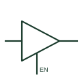
Three-state logic buffer
A digital output stage that can drive logical states or enter its documented high-impedance state.
Schematic
Inverter triangle with an enable lead and bubble entering its side, driving a bus only when enabled.
In plain English
The three-state inverter is a triangle with an output bubble and a control lead entering the sloping side. A bubble on the control lead means output enable is active low, which is the arrangement on many octal line drivers. When disabled, the output is high impedance.
On bus schematics these devices are usually drawn in groups of eight with a shared enable. Drafters should label the enable net once for the group and show which controller output drives it, so the reader can see when the bus is driven.
The symbol does not show bus hold, pull-up or pull-down arrangements needed to keep a disabled bus at a defined level. Those components must be drawn separately.
Inverter triangle with an enable lead and bubble entering its side, driving a bus only when enabled. The non-inverting three-state buffer has no output bubble.
Read the source: SNx4HC240 octal buffers and line drivers with 3-state outputs · Overview of IEEE Standard 91-1984: explanation of logic symbols (SDYZ001A)
Distinctive-shape form as used in IEEE/ANSI-style schematics and manufacturer data books. Independent educational drawing; exact standard geometry and compliance are not asserted.
Shown as an independently authored educational illustration. Use the cited publication and drawing legend to verify the required drafting form.
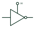
The three-state inverter is a triangle with an output bubble and a control lead entering the sloping side. A bubble on the control lead means output enable is active low, which is the arrangement on many octal line drivers. When disabled, the output is high impedance.
On bus schematics these devices are usually drawn in groups of eight with a shared enable. Drafters should label the enable net once for the group and show which controller output drives it, so the reader can see when the bus is driven.
The symbol does not show bus hold, pull-up or pull-down arrangements needed to keep a disabled bus at a defined level. Those components must be drawn separately.
The non-inverting three-state buffer has no output bubble.
These public references support the explanation and provide further detail. Their graphics and downloadable files remain with their publishers.
Manufacturer documentation for inverting octal buffers with three-state outputs.
Three-state output and EN behaviour.
This illustration was authored independently by Elora Grid to explain the concept. It is not reproduced from a customer drawing, an official standard graphic or a manufacturer CAD file. Its correspondence to an exact IEC or IEEE symbol identifier has not been certified.
SVG and DXF downloads contain this original artwork. DXF uses unscaled drawing units; a GA envelope supplies no product dimensions, clearances or fabrication information. Original artwork is available under CC BY 4.0. Third-party references retain their own terms.
A digital output stage that can drive logical states or enter its documented high-impedance state.
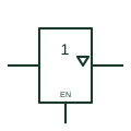
IEC buffer whose output carries the three-state triangle and is controlled by an EN input.
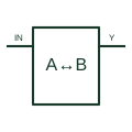
Drives data between two digital buses according to the selected direction and enable conditions.
Elora Grid helps electrical teams work with drawings, specifications and equipment information. Explore the drafting workflow or join the early-access waitlist.