3STATE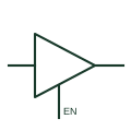
Three-state logic buffer
A digital output stage that can drive logical states or enter its documented high-impedance state.
Schematic
IEC buffer whose output carries the three-state triangle and is controlled by an EN input.
In plain English
The three-state buffer is drawn as a 1 element with a small downward triangle inside the outline next to the output, and an EN input. When EN is at its internal 1 state the output follows the input; at its internal 0 state the output goes to its external high-impedance state while the internal logic state is retained.
These elements appear where several drivers share a bus, such as data lines between controller cards. The drawing should make clear which signal drives each EN input and how the design prevents two drivers being enabled together, since the symbol itself does not show arbitration.
A negated EN input means the enable is active low, which is how many devices are supplied. Read the input marking carefully; reversing the enable sense would put a buffer on the bus at the wrong time.
IEC buffer whose output carries the three-state triangle and is controlled by an EN input. An open-circuit output uses a diamond additional drawing mark and has no high-impedance logic state of its own; the three-state triangle is different.
Read the source: Overview of IEEE Standard 91-1984: explanation of logic symbols (SDYZ001A) · SN74HC125 — three-state buffers
Qualifying-symbol and dependency conventions as explained in TI's public overview of IEEE Std 91-1984, which incorporates IEC 617-12 work. Independent educational drawing; not certified IEC geometry or an IEC database identifier. The counterpart is the matching functional concept; no equivalence of every detailed standard graphic is asserted.
Shown as an independently authored educational illustration. Use the cited publication and drawing legend to verify the required drafting form.
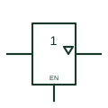
The three-state buffer is drawn as a 1 element with a small downward triangle inside the outline next to the output, and an EN input. When EN is at its internal 1 state the output follows the input; at its internal 0 state the output goes to its external high-impedance state while the internal logic state is retained.
These elements appear where several drivers share a bus, such as data lines between controller cards. The drawing should make clear which signal drives each EN input and how the design prevents two drivers being enabled together, since the symbol itself does not show arbitration.
A negated EN input means the enable is active low, which is how many devices are supplied. Read the input marking carefully; reversing the enable sense would put a buffer on the bus at the wrong time.
An open-circuit output uses a diamond qualifier and has no high-impedance logic state of its own; the three-state triangle is different.
These public references support the explanation and provide further detail. Their graphics and downloadable files remain with their publishers.
Explains the three-state qualifier and EN input effects.
Manufacturer three-state buffer documentation.
This illustration was authored independently by Elora Grid to explain the concept. It is not reproduced from a customer drawing, an official standard graphic or a manufacturer CAD file. Its correspondence to an exact IEC or IEEE symbol identifier has not been certified.
SVG and DXF downloads contain this original artwork. DXF uses unscaled drawing units; a GA envelope supplies no product dimensions, clearances or fabrication information. Original artwork is available under CC BY 4.0. Third-party references retain their own terms.
A digital output stage that can drive logical states or enter its documented high-impedance state.
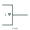
Downward triangle inside an outline marking an output that can enter a high-impedance state.
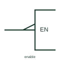
Input labelled EN that enables all outputs of the element when at its internal 1 state.
Elora Grid helps electrical teams work with drawings, specifications and equipment information. Explore the drafting workflow or join the early-access waitlist.