TX
Power transformer
Equipment transferring electrical power between winding circuits.
SLD / Schematic
An independently authored application reference. The drawing shows the named function or circuit relationship; use the project legend and selected equipment documentation for its drafting form and connections.
Browse this installation focusIn plain English
Groups the documented integrated primary functions within a selected hybrid switching module.
In a switchyard equipment diagram, the primary reference identifies the electrical role of an installed component while the linked equipment schedule and manufacturer drawing supply its exact construction and dimensions. For this reference, the drawing identifies “Module primary connections” at the input and “Integrated switching functions” at the output. Internal boundaries follow the manufacturer configuration.
Start at the named input: Module primary connections. Identify its source device or document and the state represented on the drawing. Follow the named output: Integrated switching functions. Cross-reference its destination and separate the command from confirmation that the equipment responded.
Read the source: Gas-insulated switchgear
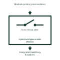
Groups the documented integrated primary functions within a selected hybrid switching module. High-voltage primary equipment carries, interrupts, measures or conditions the main power circuit. Its function, insulation arrangement and equipment boundaries need to be distinguished from the secondary signals used to control it.
In a switchyard equipment diagram, the primary reference identifies the electrical role of an installed component while the linked equipment schedule and manufacturer drawing supply its exact construction and dimensions. For this reference, the drawing identifies “Module primary connections” at the input and “Integrated switching functions” at the output. Internal boundaries follow the manufacturer configuration.
Read the connected power path before interpreting a secondary output or alarm. These original educational component references provide no product dimensions, dielectric rating, installation clearance or construction approval. The functional block is an independent explanation of this named application. Equipment-specific ratings, terminal connections and operating conditions must be established in the project documentation.
Internal boundaries follow the manufacturer configuration. This reference describes the named application; it does not establish a new IEC graphical symbol, an ANSI device-function number or an exact manufacturer connection diagram.
These public references support the explanation and provide further detail. Their graphics and downloadable files remain with their publishers.
Public technical context for high-voltage primary equipment references. Primary switching equipment and instrument-transformer interfaces. The application text and educational graphic are independently authored; the publisher does not certify this representation.
This illustration was authored independently by Elora Grid to explain the concept. It is not reproduced from a customer drawing, an official standard graphic or a manufacturer CAD file. Its correspondence to an exact IEC or IEEE symbol identifier has not been certified.
SVG and DXF downloads contain this original artwork. Original artwork is available under CC BY 4.0. Third-party references retain their own terms.
Equipment transferring electrical power between winding circuits.
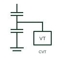
An instrument transformer using a capacitive voltage divider and an electromagnetic unit to supply documented voltage measurement or protection signals.
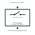
Identifies the circuit-breaker functional compartment within the assigned gas-insulated assembly.
Elora Grid helps electrical teams work with drawings, specifications and equipment information. Explore the drafting workflow or join the early-access waitlist.