ROM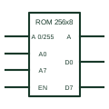
IEC read-only memory (ROM)
IEC element marked ROM with grouped address inputs and data outputs that read the addressed word.
IEC
IEC element marked RAM with address grouping, a write control input and A-labelled data inputs and outputs.
In plain English
A RAM symbol carries the RAM additional drawing mark and organisation. Address inputs form an A group; a write input is labelled with control dependency, and data inputs are labelled A plus the control number and D, meaning data is written to the addressed word when the control is active. Data outputs are labelled A.
TI's overview builds a 16-word by 4-bit memory from latches to explain this notation. On drawings, RAM symbols document buffers in communication modules and processor boards.
The symbol does not state whether the memory is static or dynamic, its retention behaviour, or any battery backup. Note those where data must survive power loss.
IEC element marked RAM with address grouping, a write control input and A-labelled data inputs and outputs. ROM has no write inputs; FIFO memory has no address inputs.
Read the source: Overview of IEEE Standard 91-1984: explanation of logic symbols (SDYZ001A)
Qualifying-symbol and dependency conventions as explained in TI's public overview of IEEE Std 91-1984, which incorporates IEC 617-12 work. Independent educational drawing; not certified IEC geometry or an IEC database identifier.
Shown as an independently authored educational illustration. Use the cited publication and drawing legend to verify the required drafting form.
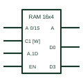
A RAM symbol carries the RAM qualifier and organisation. Address inputs form an A group; a write input is labelled with control dependency, and data inputs are labelled A plus the control number and D, meaning data is written to the addressed word when the control is active. Data outputs are labelled A.
TI's overview builds a 16-word by 4-bit memory from latches to explain this notation. On drawings, RAM symbols document buffers in communication modules and processor boards.
The symbol does not state whether the memory is static or dynamic, its retention behaviour, or any battery backup. Note those where data must survive power loss.
ROM has no write inputs; FIFO memory has no address inputs.
These public references support the explanation and provide further detail. Their graphics and downloadable files remain with their publishers.
RAM qualifier and the memory array example using A dependency.
This illustration was authored independently by Elora Grid to explain the concept. It is not reproduced from a customer drawing, an official standard graphic or a manufacturer CAD file. Its correspondence to an exact IEC or IEEE symbol identifier has not been certified.
SVG and DXF downloads contain this original artwork. DXF uses unscaled drawing units; a GA envelope supplies no product dimensions, clearances or fabrication information. Original artwork is available under CC BY 4.0. Third-party references retain their own terms.
IEC element marked ROM with grouped address inputs and data outputs that read the addressed word.
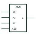
Dependency label A used on memory symbols to show which word of an array the address inputs select.
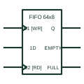
IEC element marked FIFO that stores words in arrival order and reads them out in the same order.
Elora Grid helps electrical teams work with drawings, specifications and equipment information. Explore the drafting workflow or join the early-access waitlist.