WDT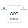
Watchdog timer
Supervises a qualifying activity signal and operates its output when the documented watchdog timing condition is violated.
Schematic
In plain English
A power-good signal reports whether the source's specified acceptable-supply conditions are satisfied.
A downstream circuit can use this status when deciding whether to enable its operation.
Draw power-good as a status signal from its source or supervisor to the receiving controller. It is information about specified acceptable conditions, not the supply conductor itself. State the active level and timing requirements from the selected source so the receiving circuit interprets it correctly.
Not generally. It reports whether the generating device’s defined conditions are satisfied. It does not automatically report spare capacity, complete system readiness or a continuously measured power value.
Read the source: Supply supervision and reset
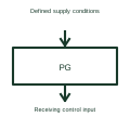
Power-good timing and thresholds come from the selected source or supervisor.
These public references support the explanation and provide further detail. Their graphics and downloadable files remain with their publishers.
Supply supervision and reset: public technical context for the named function. Product and compliance details remain with the publisher.
This illustration was authored independently by Elora Grid to explain the concept. It is not reproduced from a customer drawing, an official standard graphic or a manufacturer CAD file. Its correspondence to an exact IEC or IEEE symbol identifier has not been certified.
SVG and DXF downloads contain this original artwork. DXF uses unscaled drawing units; a GA envelope supplies no product dimensions, clearances or fabrication information. Original artwork is available under CC BY 4.0. Third-party references retain their own terms.
Supervises a qualifying activity signal and operates its output when the documented watchdog timing condition is violated.
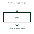
A voltage supervisor checks a supply against specified conditions and produces a status or reset signal.
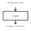
A window supervisor checks whether a monitored voltage stays between its specified lower and upper limits.
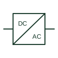
An identified interface converting electrical power between documented circuit forms.
Elora Grid helps electrical teams work with drawings, specifications and equipment information. Explore the drafting workflow or join the early-access waitlist.