MGMC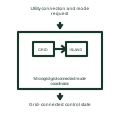
Microgrid grid-connected mode coordinator
Coordinates the defined source and load controls while the utility interconnection is established.
Functional block
Explore electrical symbols, functional blocks and circuit arrangements for switchgear, switchrooms, substations, switchyards and microgrids. Detailed explanations, drawing notes, public sources and original SVG/DXF illustrations.
Coordinates the defined source and load controls while the utility interconnection is established.
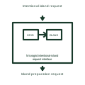
Receives the authorized request to prepare the defined microgrid for separation from the utility.
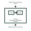
Applies the documented control response to an externally initiated loss of utility connection.
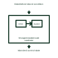
Coordinates the defined local voltage, frequency and resource controls after the island state is established.
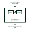
Checks the defined prerequisites before attempting the selected return to grid connection.
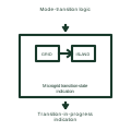
Reports that the controller is between its defined stable operating modes.
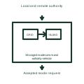
Selects the authorized origin of operating-mode requests according to the control philosophy.
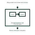
Detects disagreement between the requested mode and the established topology or resource state.
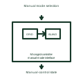
Identifies the documented manual control authority and its assigned automatic restraints.
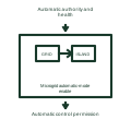
Permits the defined automatic coordination when its required authority and health inputs are satisfied.
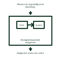
Assigns the selected resources to their documented grid-forming or following control roles.
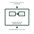
Selects the available source assigned to establish the island voltage and frequency reference.
Understand symbols, equipment tags and function numbers—and know when a generic object needs a manufacturer drawing.
In plain English
Electrical symbols are shorthand for equipment, functions and connections. They let you follow how a circuit works without drawing every physical detail.
On a microgrid single-line diagram, a current-transformer symbol marks a measurement point and a breaker symbol marks where a circuit can be disconnected. Their labels identify the actual equipment.
Follow the connected lines to trace power or control signals. Use the project legend to interpret symbols and the selected manufacturer's drawings for dimensions and terminal connections.