Board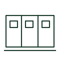
Switchboard
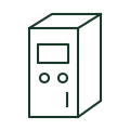
A distribution assembly represented by a generic envelope in an arrangement drawing.
GA objects
An HMI presents operating information and control interfaces to the user.
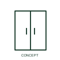
An HMI presents operating information and control interfaces to the user.
Coordinate the door cut-out, mounting clips, rear depth and cable bend zone. The GA locates the physical item; the associated schematic or equipment schedule records its electrical interfaces.
The preview is independent educational geometry and is not a manufacturer outline, fabrication drawing or verified standard graphic. Obtain the applicable model drawing from the cited official source before making a dimensional layout.
Display diagonal is different from cut-out and overall enclosure dimensions.
These public references support the explanation and provide further detail. Their graphics and downloadable files remain with their publishers.
Public manufacturer or design reference relevant to this equipment class.
This illustration was authored independently by Elora Grid to explain the concept. It is not reproduced from a customer drawing, an official standard graphic or a manufacturer CAD file. Its correspondence to an exact IEC or IEEE symbol identifier has not been certified.
SVG and DXF downloads contain this original artwork. DXF uses unscaled drawing units; a GA envelope supplies no product dimensions, clearances or fabrication information. Original artwork is available under CC BY 4.0. Third-party references retain their own terms.
Elora Grid helps electrical teams work with drawings, specifications and equipment information. Explore the drafting workflow or join the early-access waitlist.