SR-LATCH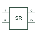
Set-reset latch
Retains a digital state that is changed by the defined set or reset input conditions.
Schematic
Two NOR gates cross-coupled to form an SR latch with active-high set and reset inputs.
In plain English
Two NOR gates with each output fed back to an input of the other form an SR latch with active-high inputs. A high on set drives Q high, a high on reset drives Q low, and both low holds the state. Both high forces both outputs low and is normally treated as invalid.
This form appears in educational schematics and in discrete logic designs where a spare quad NOR package provides a latch. It is the natural form when the set and reset signals are active-high commands.
Like the NAND form, it shows construction rather than a guaranteed power-up state. A defined start-up condition needs extra circuitry or a reset pulse.
Two NOR gates cross-coupled to form an SR latch with active-high set and reset inputs. The cross-coupled NAND latch responds to active-low inputs.
Read the source: SN74HC02 — NOR gate logic
Distinctive-shape form as used in IEEE/ANSI-style schematics and manufacturer data books. Independent educational drawing; exact standard geometry and compliance are not asserted. The counterpart is the matching functional concept; no equivalence of every detailed standard graphic is asserted.
Shown as an independently authored educational illustration. Use the cited publication and drawing legend to verify the required drafting form.
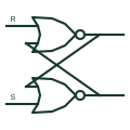
Two NOR gates with each output fed back to an input of the other form an SR latch with active-high inputs. A high on set drives Q high, a high on reset drives Q low, and both low holds the state. Both high forces both outputs low and is normally treated as invalid.
This form appears in educational schematics and in discrete logic designs where a spare quad NOR package provides a latch. It is the natural form when the set and reset signals are active-high commands.
Like the NAND form, it shows construction rather than a guaranteed power-up state. A defined start-up condition needs extra circuitry or a reset pulse.
The cross-coupled NAND latch responds to active-low inputs.
These public references support the explanation and provide further detail. Their graphics and downloadable files remain with their publishers.
NOR gate documentation for the building block.
This illustration was authored independently by Elora Grid to explain the concept. It is not reproduced from a customer drawing, an official standard graphic or a manufacturer CAD file. Its correspondence to an exact IEC or IEEE symbol identifier has not been certified.
SVG and DXF downloads contain this original artwork. DXF uses unscaled drawing units; a GA envelope supplies no product dimensions, clearances or fabrication information. Original artwork is available under CC BY 4.0. Third-party references retain their own terms.
Retains a digital state that is changed by the defined set or reset input conditions.
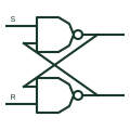
Two NAND gates with outputs fed back to each other, forming an SR latch with active-low set and reset.
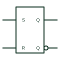
Rectangular IEC bistable with S and R inputs that set or reset the stored state immediately.
Elora Grid helps electrical teams work with drawings, specifications and equipment information. Explore the drafting workflow or join the early-access waitlist.